Engineers Garage

  • Projects and Tutorials
    • Electronic Projects
      • 8051
      • Arduino
      • ARM
      • AVR
      • PIC
      • Raspberry pi
      • STM32
    • Tutorials
    • Circuit Design
    • Project Videos
    • Components
  • Articles
    • Tech Articles
    • Insight
    • Invention Stories
    • How to
    • What Is
  • News
    • Electronic Products News
    • DIY Reviews
    • Guest Post
  • Forums
    • EDABoard.com
    • Electro-Tech-Online
    • EG Forum Archive
  • Digi-Key Store
    • Cables, Wires
    • Connectors, Interconnect
    • Discrete
    • Electromechanical
    • Embedded Computers
    • Enclosures, Hardware, Office
    • Integrated Circuits (ICs)
    • Isolators
    • LED/Optoelectronics
    • Passive
    • Power, Circuit Protection
    • Programmers
    • RF, Wireless
    • Semiconductors
    • Sensors, Transducers
    • Test Products
    • Tools
  • EE Resources
    • DesignFast
    • LEAP Awards
    • Oscilloscope Product Finder
    • White Papers
    • Webinars
  • EE Learning Center
  • Women in Engineering

Insight – How Desoldering Pump works

By Ashutosh Bhatt


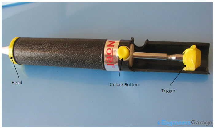
DESOLDERING is the process of removing soldered components from a circuit made on PCB. Desoldering pump along with the soldering iron is used for this purpose. A desoldering pump also known as solder sucker is a small mechanical device which sucks the liquid/molten solder from the joint where the components are mounted. In order to desolder a component from the PCB, we first heat up the solder joint with the soldering iron till the solder liquefies/melts. At the same moment we actuate the soldering pump by pressing the trigger lever and bring the tip over the molten metal and pull the trigger back by pressing a button shown in the below image. At this instant the lever is pulled back and the tip of the pump sucks the molten solder. This process is repeated until all the residue solder is sucked by the pump and the hole on the PCB is clear to solder a fresh component.
Desoldering Pump and its Parts

Fig. 1: Desoldering Pump and its Parts

Above image shows a desoldering pump – head, trigger and button of the soldering pump are marked. To actuate the pump the lever is pressed until there is a click sound which indicates that the lever will remain locked in the same position.
Mechanical Arrangement of Pump Head

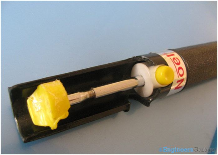
Fig. 2: Mechanical Arrangement of Pump Head

 
Design of Pump Head
 
Fig. 3: Design of Pump Head
 
The desoldering pump’s bottom head contains a hole through which the molten solder is sucked when the pump is triggered. The head is designed such that the extracted solder does not solidify and block it, consequently the sucked metal can be removed and discarded easily.

 Internal Structure
Internal Structure of Pump

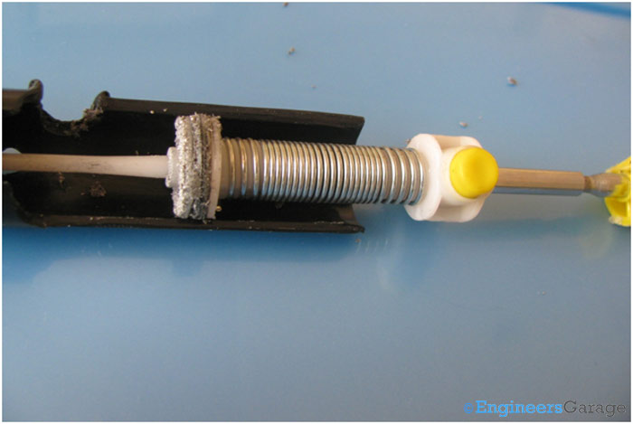
Fig. 4: Internal Structure of Pump

Removing the outer case reveals its major components – spring, spring lever, a mechanical lock and a piston to draw the solder.
 
Image showing Structure of Desoldering Head
 
Fig. 5: Image showing Structure of Desoldering Head
 
The desoldering head has the structure and working similar to a syringe. The piston draws the molten solder when it is pulled back by the spring.

 Working

Spring and Lock Arrangement

Fig. 6: Spring and Lock Arrangement

 
When desoldering pump is operated, the spring gets compressed as shown in the above image. At this moment if the button is pressed the mechanical lock will be opened and spring will extend back to the normal position pulling the piston towards the lever.
 

Images showing working of Mechanical Lock


Fig. 7: Images showing working of Mechanical Lock


Working of the mechanical lock is shown in the image. If the lever is pressed a special shaped edging on the lever is wedged with mechanical lock. As we press the yellow button the lock will be slightly moved away clearing the way for lever to move back. Another small spring is used to keep the lock in a fixed position.
 
Close View of Mechanical Lock
 
Fig. 8: Close View of Mechanical Lock
 
The mechanical lock is more clearly shown in the above image. 

Structure of Piston

Image Showing Structure of Piston

Fig. 9: Image Showing Structure of Piston

Structure of the piston is shown in the image. When pump is triggered, the piston creates a vacuum in the front desoldering head and allows entering the air only from the hole on the tip. As the piston moves speedily, the sudden vacuum draws the air next to the tip and with the air the molten solder is also drawn. The sucked solder is discarded by pressing the lever. The same process is practiced few times to remove the old solder completely.

Filed Under: Insight
Tagged With: desoldering, desoldering pump, pump, solder
 

Questions related to this article?
👉Ask and discuss on Electro-Tech-Online.com and EDAboard.com forums.


Tell Us What You Think!! Cancel reply

You must be logged in to post a comment.

HAVE A QUESTION?

Have a technical question about an article or other engineering questions? Check out our engineering forums EDABoard.com and Electro-Tech-Online.com where you can get those questions asked and answered by your peers!


Featured Tutorials

  • Designing Gate Driver Circuit and Switching Mechanism for Modified Sine Wave Inverter – (Part 9/17)
  • Completing Modified Sine Wave Inverter Design with Full Bridge Circuit and Step Up Transformer – (Part 10/17)
  • Designing an Offline UPS – Part (12 /17)
  • How to reduce Switching Time of a Relay – (Part 15/17)
  • Testing MOSFET – (Part 16/17)
  • Driving High Side MOSFET using Bootstrap Circuitry – (Part 17/17)

Stay Up To Date

Newsletter Signup

Sign up and receive our weekly newsletter for latest Tech articles, Electronics Projects, Tutorial series and other insightful tech content.

EE Training Center Classrooms

EE Classrooms

Recent Articles

  • Designing Gate Driver Circuit and Switching Mechanism for Modified Sine Wave Inverter – (Part 9/17)
  • Completing Modified Sine Wave Inverter Design with Full Bridge Circuit and Step Up Transformer – (Part 10/17)
  • Designing an Offline UPS – Part (12 /17)
  • How to reduce Switching Time of a Relay – (Part 15/17)
  • Testing MOSFET – (Part 16/17)

Most Popular

5G 555 timer circuit 8051 ai Arduino atmega16 automotive avr dc motor display Electronic Part Electronic Parts Fujitsu ic infineontechnologies integratedcircuit Intel IoT ir lcd ldr led maximintegratedproducts microchip microchiptechnology Microchip Technology microcontroller microcontrollers mosfet motor powermanagement Raspberry Pi remote renesaselectronics Research robot samsung semiconductor sensor software STMicroelectronics switch Technology vishayintertechnology wireless

RSS EDABOARD.com Discussions

  • Do you use C++ for device drivers in embedded systems?
  • MAX5389 resetting by noise
  • Help with Verilog replicate operator
  • Verilog/SV: Using an array as a set of individual registers and not RAM
  • How did they made the old manuals or magazines sketches?

RSS Electro-Tech-Online.com Discussions

  • Relaxation oscillator with neon or...
  • MOSFET gets hot and burns
  • LCD display on PICDEM 2 Plus board
  • software PWM
  • Positive and negative sides of voltage source
Engineers Garage
  • Analog IC TIps
  • Connector Tips
  • DesignFast
  • EDABoard Forums
  • EE World Online
  • Electro-Tech-Online Forums
  • Microcontroller Tips
  • Power Electronic Tips
  • Sensor Tips
  • Test and Measurement Tips
  • 5G Technology World
  • About Us
  • Contact Us
  • Advertise

Copyright © 2022 WTWH Media LLC. All Rights Reserved. The material on this site may not be reproduced, distributed, transmitted, cached or otherwise used, except with the prior written permission of WTWH Media
Privacy Policy | Advertising | About Us

Search Engineers Garage

  • Projects and Tutorials
    • Electronic Projects
      • 8051
      • Arduino
      • ARM
      • AVR
      • PIC
      • Raspberry pi
      • STM32
    • Tutorials
    • Circuit Design
    • Project Videos
    • Components
  • Articles
    • Tech Articles
    • Insight
    • Invention Stories
    • How to
    • What Is
  • News
    • Electronic Products News
    • DIY Reviews
    • Guest Post
  • Forums
    • EDABoard.com
    • Electro-Tech-Online
    • EG Forum Archive
  • Digi-Key Store
    • Cables, Wires
    • Connectors, Interconnect
    • Discrete
    • Electromechanical
    • Embedded Computers
    • Enclosures, Hardware, Office
    • Integrated Circuits (ICs)
    • Isolators
    • LED/Optoelectronics
    • Passive
    • Power, Circuit Protection
    • Programmers
    • RF, Wireless
    • Semiconductors
    • Sensors, Transducers
    • Test Products
    • Tools
  • EE Resources
    • DesignFast
    • LEAP Awards
    • Oscilloscope Product Finder
    • White Papers
    • Webinars
  • EE Learning Center
  • Women in Engineering