Number combination lock is like a mystery game of combinations and sequences. With the use of mathematical logics and basic laws of physics (balancing of forces) the old traditional padlocks have been replaced by new and modified number combination lock. Padlocks are the portable locks that were designed to defend against any theft, vandalism or sabotage but with passage of time they became part of day to day life as a safety measure. Padlocks used earlier were heavy and required key to unlock but with number combination lock it becomes easy to handle the system as only thing that is required is a code which can activate or deactivate the lock. Now, all one has to do is set their code and activate the lock. Lets take the insight of number combination lock in the following section stepwise from its outer parts to the innermost components.
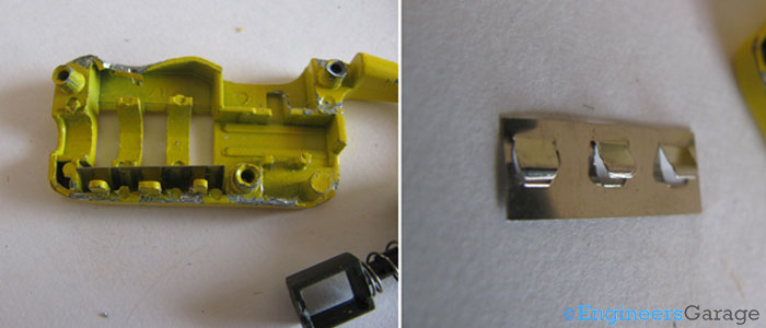
Fig. 1: A Typical Number Combination Lock
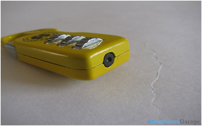
Fig. 2: Image Showing Cap Position In External Casing Of Number Combination Lock
Internal Structure
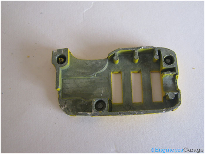
Fig. 3: Picture Showing Rear Design Of Combination Lock Casing
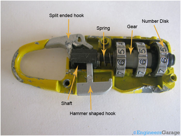
Fig. 4: Diagrammatical Picture Showing Various Parts of A Number Combination Lock
Hooks and their orientation
There are two hooks present inside the internal casing, one is split ended and other one is hammer shaped. One end of split ended hook is connected to the shackle and other end goes between the outer casing and the plastic shaft while hammer shaped is positioned inside the hollow portion of the shaft. These hooks are placed close to each other.
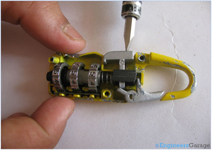
Fig. 5: Image Showing Hammer Position In A Number Combination Lock
Shaft & Number Disks
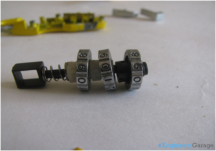
Fig. 6: Image Showing Arrangement of Numbered Disks, Gears, and Shaft Inside Combination Lock
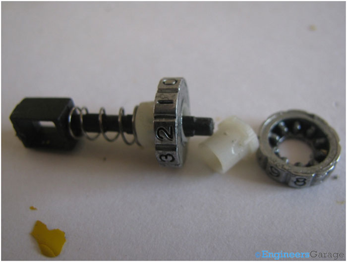
Fig. 7: White Gears That Are Present Under Numbered Disks
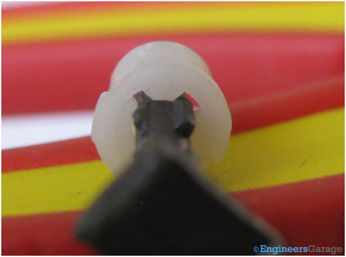
Fig. 8: Shaft Present At The Core of Number Combination Lock
Gears
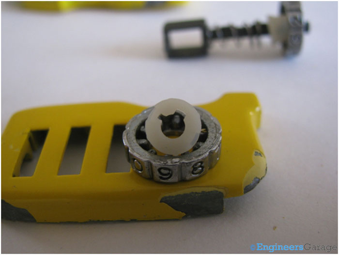
Fig. 9: Closer View of Gears Present In Combination Locks

Fig. 10: Picture Showing How White Gear Teeth Hold The Shaft Inside Combination Lock
Structure of Shaft

Fig. 11: Picture Showing Placement of Numbered Disk over Shaft
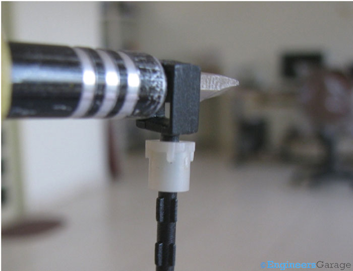
Fig. 12: Typical Structure of Shaft
Metal Plate

Fig. 13: Image Showing Closer View of Metal Plate Placed Inside Plastic Casing

Fig. 14: Closer View of A Typical Number Combination Lock
Mechanism for Opening the Lock
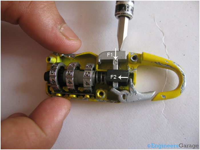
Fig. 15: Explanatory Image Showing Locking Mechanism of A Number Combination Lock
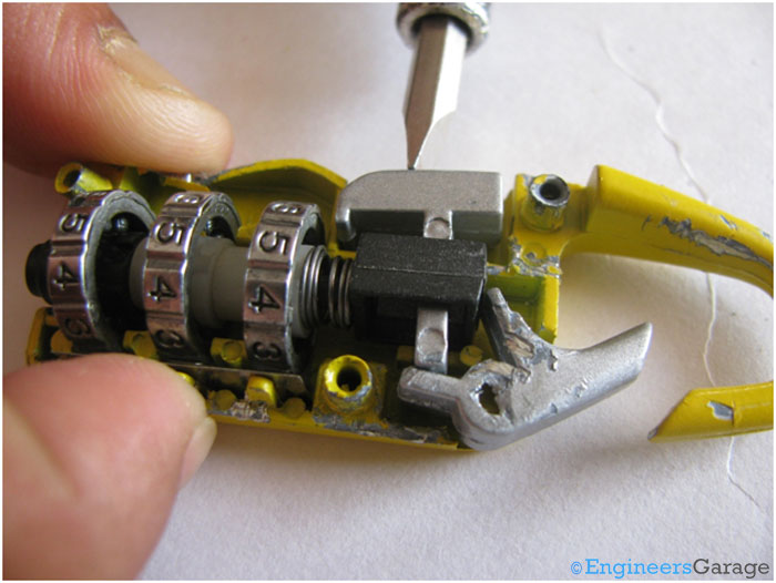
Fig. 16: Image Showing What Happens When Force Is Applied On Hammer Shaped Hook
Changing the Code
Filed Under: Insight


Questions related to this article?
👉Ask and discuss on EDAboard.com and Electro-Tech-Online.com forums.
Tell Us What You Think!!
You must be logged in to post a comment.