Insight – How Pulse Transformer works
Transformers have now become an integral part of any electronic or electrical circuit. From applications of few voltages like phone adaptors to large ones like power transmission lines, transformers are always one of the inevitable requirements. Depending on the requirements, transformers are now vastly divided into many types. This Insight will detail about one of such application specific transformer, pulse transformer.
Pulse transformers work in the same way as any other transformer does, but they have outputs in digital or pulsed waveforms, such as square wave or rectangular wave. These transformers are used in digital communications, for camera flashes, radar systems and such fields where pulsed form of voltage is required. They are enough varied in terms of voltage as per their application and their working can as low as 8V or as high as 200kV depending on their use. They usually have more number of secondary coils than primary.
Outer Casing
Cased in a plastic shell, the transformer presented here is PT4503 which has two secondary coils over one primary coil. The turn ratio is usually mentioned on the packaging of the transformer. In this case, it is 1:1:1 as mentioned in the front portion of the transformer. As it has two secondary windings which are isolated in terms of voltage transfer and electrical output, it is an isolation type transformer.
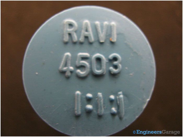
A lateral look on the transformer will give an appearance of a satellite as it has as much as 6 legs. Out of these 6 legs, 2 are connected to the primary while the other 4 represent the two pairs of secondary coils.

The rear side of the transformer has a layer of adhesive that holds the legs of the transformer and keeps them tightly mechanically attached to the body of the transformer.

[header = Shell]
The shell is strongly adhered to the inner surface of the transformer keeping it safe from the ambient influences. On removing the shell, another dense plastic packaging is found. It is semi translucent as one can partially see the inner components of the transformer through it. Shown in the image below is the upper view of the transformer core that appears when the plastic casing is removed.
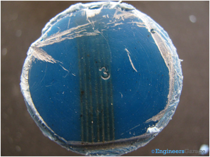
However from the lateral view, no parts of the transformer are visible indicating the high density of the plastic which is around it. The main reason for this thorough condense packaging is to provide better insulation so that in cases of high voltage no inductive and capacitive leakages take place as well no unwanted effects like moisture or humidity reduce the working efficiency of the transformer.

On penetration into the glass epoxy resin, the legs are again found to be strongly adhered to it and for this purpose another adhesive is used. As the legs are mainly responsible for high power input as well as output, they are required to be as correctly placed as possible otherwise device might have to incur unpredictable power losses.
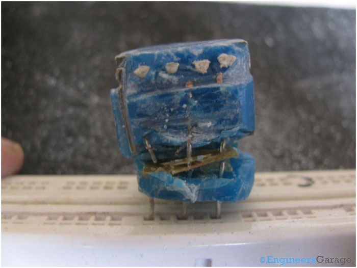
Through this adhesive, the legs are soldered to the up so that they could be placed near the core of the transformer.

The image below displays how the soldering keeps the legs connected to the transformer.
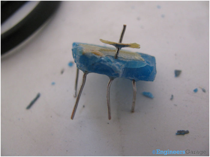
The upper surface details with the core plates as well as the insulator attached to them can be seen with a slight more excavation.
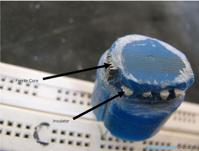
The insulator makes sure that the coils don’t get shuffled as well as avoids the legs to establish contact with the core as only coils should be wound around them. It also separates the output ports that come through the secondary windings. Since, there are two secondary windings, a proper electrical isolation is required to be kept.

The following image depicts how coil is wound on the legs of the transformer and how the insulator separates the legs from the core.

[header = Coils]
The proper appearance of the coil appears only after most of the glass epoxy resin is taken off the transformer. The coil has the insulator projections on its upper and lower parts while the core is present on the sides. Coil is insulated from the core through the very same resin that covers the transformer circuitry.
To avoid loss due to eddy currents, the coil is fairly laminated so that no sustainable induced voltage effects affect the efficiency of the transformer.

The core in this transformer is W shaped, so the coils have been wound around its centre. The outer coil is the primary while secondary is separated from it through a thin insulating sheath.

After the coil is taken off the core, the sheath can be carefully observed and primary and secondary windings can be easily figured out.

From the rear side of the coil, the coverage of the glass epoxy resin can be seen as it still holds tightly to the copper windings of the transformer.
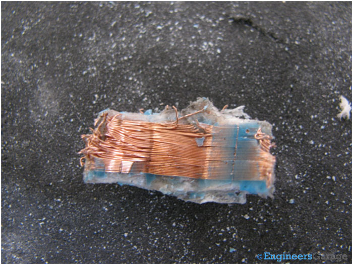
[header = Transformer Core]
After removing the coils, the core of the transformer can be studied deeply. Shown below is the single “W” shaped ferrite transformer core. The cores are painted so as to avoid their oxidization.
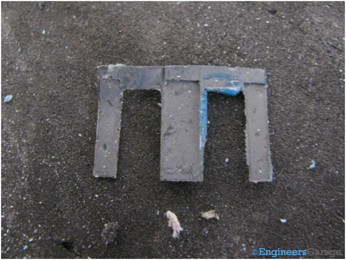
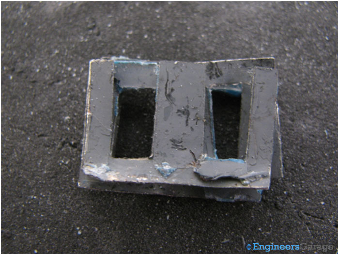
These cores are alternatively placed near each other forming the structure shown below.
Filed Under: Insight


Questions related to this article?
👉Ask and discuss on Electro-Tech-Online.com and EDAboard.com forums.
Tell Us What You Think!!
You must be logged in to post a comment.