The Uninterruptible Power Supply (UPS) is an electronics device which supplies power to a load when main supplies or input power source fails. It not only acts as an emergency power source for the appliances, it serves to resolve common power problems too. Any UPS has a power storage element which stores energy in the form of chemical energy like the energy is stored in batteries.
It is like energy is stored in the form of motion in a flywheel. That is why these devices are also called battery backup or flywheel backup. The UPS not only provides emergency power, they also help to sort out common power related issues like providing protection from input power interruptions, protection from overvoltage, output voltage regulation and stabilization.
Different UPS models have different ability to supply power to the load. The degree of ability totally depends on the how much charge is stored inside the UPS. For example, the UPS designed for computers can supply power only for some small duration of time when the power goes off but that time is sufficient enough to save files on which the user may be working. So, for obvious reasons, the charge storage ability of any UPS is determined during its design considering its application.
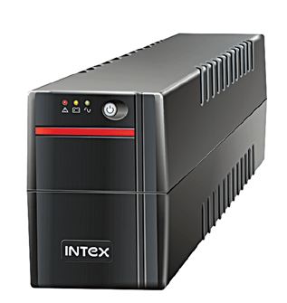
Fig. 1: Typical image of a UPS
Difference in UPS and normal emergency power source
The traditional emergency power sources use generators with transfer switch for powering the appliance when main supply fails. It can provide power for hours till the fuel is available in the generator. However, this has a drawback. The appliance on connecting to the generator experiences interruption during failure of the main power source. This interruption happens because the generator has to turn on for resuming power. Depending on the type of switching mechanism, there is an interruption in the power supply to the load.
Contrary to emergency power supplies, the Uninterruptible Power Supply (UPS) delivers continuous power to the appliance without any interruption by using battery or flywheel. But the duration of time for which UPS supplies power to the appliance is limited depending on the size and number of battery or flywheel used.
The use of UPS is quite popular in applications where the appliances can not afford any kind of interruption. Like in health care units, medical equipment, IT offices, telecommunication, data centers, banks and at many more places where an uninterrupted power supply is needed.
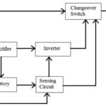
In this series, a UPS will be designed which will have a battery as storing element and can supply power to the appliance in case of power failure. The design of a UPS can be broken down into different sections having a distinct role in the functioning of the UPS (as shown in the image below).

Fig. 2: Image showing Building Blocks of a UPS circuit
The UPS designed in this series will have four circuit section as follow –
1. Charger –
First of all, a charger will be designed for charging the energy storage element which is the battery in this case. As there are two types of batteries popularly used – Li-ion batteries and the Lead-Acid batteries, there will be two different charger circuits designed one for each. These battery chargers will be designed as follows –
i) Lead acid battery charger
In this battery charger circuit, a constant voltage lead-acid battery charger will be designed i.e. the charger will provide a constant voltage equal to the maximum voltage rating of the battery with the limited charging current. So in this charger, the battery will never exceed the preset charging current.
Below is the charging algorithm of the battery which shows the current and voltage of the battery.
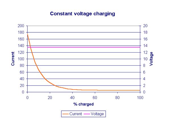
Fig. 3: Graph showing Constant Voltage Charging for Lead Acid Batteries
ii) Li-ion Battery Charger
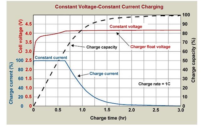
Unlike the Lead-Acid batteries, the Li-ion batteries require charging through a constant current-constant voltage method. Designing a Li-ion battery charger will need an intelligent circuitry which will sense the current as well as the voltage of the battery. Initially, the charging circuit will be in a constant current mode and will provide a constant current to the battery. When the battery voltage will reach the pre-set voltage or maximum rated voltage then the charger will switch to constant voltage mode. The current in this mode will slowly start dropping down by maintaining a constant voltage.
Below graph shows the charging algorithm of the Li-ion battery which gives a clear understanding of different charging stages.
Fig. 4: Graph showing Constant Voltage and Constant Current Charging for Li-ion Batteries
It is well known that the home appliances operates on AC voltage. But the battery used as charge storage element provides the DC power. So to convert this DC signal into AC signal, an inverter needs to be used.
The inverter is an electronics device which can convert the DC into AC. For designing UPS, there can be two types of inverters which are categorized on the basis of the shape of the AC waveform –
i) Square wave inverter –
This inverter gives a square wave at the output after converting the DC signal. The square wave inverter is cheap to design but it can be used only for low sensitive devices otherwise, they will produce humming or noise.

Fig. 5: Graph showing Output Waveform of Square Wave Inverter
ii) Modified sine wave inverter
In this type of inverter, two square waves having a phase difference of 90 degree are generated and superimposed to get a nearly sine waveform. The resultant waveform is not exactly sinusoidal but it is a three-level waveform include zero voltage level, peak positive voltage and peak negative voltage. The modified sine wave takes a pause (set at zero volts) before changing the polarity (as shown in figure below).
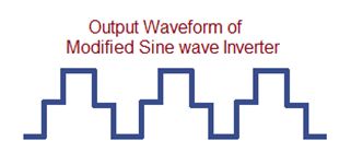
Fig. 6: Graph showing Output Waveform of Modified Sine Wave Inverter
3) Switching control
Apart from charger and inverter, UPS needs a switching mechanism by which it can switch the power source of the appliances from main power to the inverter as the power fails. There can be two types of switching control for the UPS which are as follow –
i) Offline switching/standby UPS
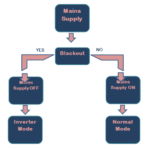
In this type of UPS system, the load is directly connected to the mains AC supply. Whenever the AC mains voltage drops down or there is a power shut down then through a switching mechanism the load as well the battery switches to the inverter. This inverter then provides AC to the load and when power resumes, the load again switches back to the mains supply. This switching mechanism can be understood graphically from the figure below –
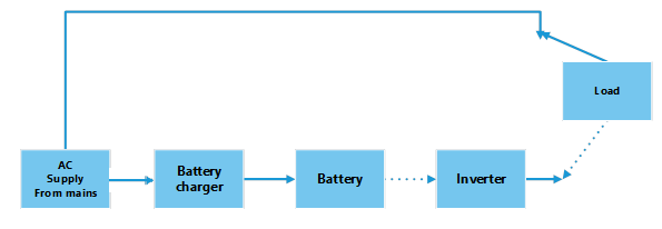
Fig. 7: Block Diagram of an Offline UPS
ii) Online switching/Double-conversion UPS
In this design, the load is always connected to the inverter. The inverter gets DC supply from the battery which is continuously charging via a battery charger. So when mains power fails the charge accumulated in the battery delivers continuous power to the appliance without any interruption.

Fig. 8: Block Diagram of Online UPS
4) BMS (Battery Management System)
In any UPS, a Battery Management System (BMS) is necessary which can monitor the battery’s state of charge and discharge, charging current and its voltage. It also protects the battery from overcharging and over discharging. So to safeguard and to increase the lifespan of the battery, the BMS should be used in UPS designs. Therefore a BMS will be designed to continuously monitor the battery status.
After this brief introduction of each building block of UPS, its time to design an electronic circuit for each block. Jump start to next tutorial, ‘Designing Lead Acid Battery Charger’ to get hands dirty with the very first UPS circuit section.
You may also like:
Filed Under: Python, Tutorials

