Engineers Garage

  • Projects and Tutorials
    • Electronic Projects
      • 8051
      • Arduino
      • ARM
      • AVR
      • PIC
      • Raspberry pi
      • STM32
    • Tutorials
    • Circuit Design
    • Project Videos
    • Components
  • Articles
    • Tech Articles
    • Insight
    • Invention Stories
    • How to
    • What Is
  • News
    • Electronic Products News
    • DIY Reviews
    • Guest Post
  • Forums
    • EDABoard.com
    • Electro-Tech-Online
    • EG Forum Archive
  • Digi-Key Store
    • Cables, Wires
    • Connectors, Interconnect
    • Discrete
    • Electromechanical
    • Embedded Computers
    • Enclosures, Hardware, Office
    • Integrated Circuits (ICs)
    • Isolators
    • LED/Optoelectronics
    • Passive
    • Power, Circuit Protection
    • Programmers
    • RF, Wireless
    • Semiconductors
    • Sensors, Transducers
    • Test Products
    • Tools
  • EE Resources
    • DesignFast
    • LEAP Awards
    • Oscilloscope Product Finder
    • White Papers
    • Webinars
  • EE Learning Center
    • Design Guides
      • WiFi & the IOT Design Guide
      • Microcontrollers Design Guide
      • State of the Art Inductors Design Guide
  • Women in Engineering

Designing an Offline UPS – Part (12 /17)

By Dikhsa

In the previous tutorial, Online UPS was assembled from its basic building blocks like Lead Acid battery Charger, Square Wave Inverter and Modified Sine Wave Inverter. Now in this tutorial, offline UPS will be designed. The Offline UPS is one of the topologies of UPS (Uninterruptible Power Supply). In UPS system, the term topology refers to the switching mechanism of the UPS system. 
Contrary to online UPS, in offline UPS, the load circuit is initially directly powered by the AC mains. On the failure of power supply, the power failure is detected by a switching circuit and the power is provided to the load through the battery and inverter after the power failure has already occurred. So, in the offline UPS, the load experiences the power cutoff once before it receives the power backup from the UPS.
So, the offline UPS has a switching mechanism for power transfer from Mains AC to the Inverter and Vice-Versa. When the mains supply is available, the load circuit draws power from the Mains Supply directly. But, when there is a blackout or power cut off from the mains, the load circuit is connected to the inverter circuit for drawing power from the charged battery. The battery itself is charged from mains supply but it does not provide power to the load circuit until the power cut is detected. This operational algorithm of an offline UPS is represented in the following flowchart – 

Flowchart representing operation of offline UPS


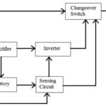
Fig. 1: Flowchart representing operation of offline UPS

The circuit of an offline UPS is not much different from the Online UPS except that the offline UPS has a switching mechanism to detect power failure and transfer power input of the load. The power failure detector and transfer switch has been designed in this offline UPS circuit using a relay circuit whose operation depends upon the status of the AC mains. The AC mains is rectified and stepped down to 12V DC to drive a relay circuit which in turns determine whether the load connects directly to the AC Mains or connects to the inverter circuit. 
There are two relays used in the switching mechanism. One relay connects the inverter inputs with the battery and other relay connects the load with the Mains Supply. The load is also connected to the Inverter output. When Mains Supply is available, the relay connecting the inverter inputs with the battery remains goes in on condition so, the inverter circuit does not draw any power from the battery as it is connected to NC point of the relay while the relay connecting the load with the Mains Supply also remain in ON condition supplying the load power from AC mains as the load is connected to the Mains Supply via NO point of the other relay. As the Mains Supply is cut off, the relay connecting the inverter inputs with the battery goes to OFF state letting the inverter draw power from the battery which is connected via NC point while the relay connecting the load with the AC mains also goes in off state cutting off the load from the AC mains as load is connected to AC Mains via NO point, so the load then draws power from the inverter output. 
Components Required – 

List of Components used in Designing Offline UPS

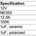
Fig. 2: List of components used in designing offline UPS

Block Diagram – 
The circuit of an offline UPS can be represented by the following block diagram – 
Block Diagram of Offline UPS
Fig. 3: Block Diagram of Offline UPS
Note that though there are two circuits designed for offline UPS, both circuits have the same block representation. 
Circuit Diagram – 
The Lead Acid battery is used in this offline UPS design. The battery charger has the following circuit diagram – 

Circuit Diagram of LM317 IC based Lead Acid Battery Charger


Fig. 4: Circuit Diagram of LM317 IC-based Lead Acid Battery Charger

The switching mechanism with the following circuit diagram is added to make the complete offline UPS –

Circuit Diagram of Offline UPS


Fig. 5: Circuit Diagram of Offline UPS

Circuit Connections – 

Since the battery charger circuit and inverter circuits have been already designed, now only these circuits need to be assembled together with the switching to make the offline UPS. For learning about the lead acid battery charger circuit, check out the following tutorial – 
Designing 12V Lead-Acid Battery Constant Voltage Limited Current Charger for UPS
For learning about the design of square wave inverter, check out the following tutorial – 
Designing Switching Mechanism with Step Up Transformer for Square Wave Inverter
For learning about the design of Modified Sine wave inverter, check out the following tutorial – 
Completing Modified Sine Wave Inverter Design with Full Bridge Circuit and Step Up Transformer
In the offline UPS based on Square wave inverter, the 7812 voltage regulator IC is connected to the output of the full-bridge rectifier. The output of the 7812 Voltage regulator is connected to the relays of the transfer switch. In the transfer switch one relay connects the inverter inputs with the battery terminals while the other relay connects the load with the Mains Supply. The inverter inputs are connected to the battery terminals via NC point of the respective relay while load is connected to the Mains Supply via NO point of the respective relay. 
Prototype of Offline UPS built using Square Wave Inverter and Lead Acid Battery Charger
Fig. 6: Prototype of Offline UPS built using Square Wave Inverter and Lead Acid Battery Charger
In the offline UPS based on Modified Sine wave inverter, circuit connections are same as that of the offline UPS based on Square Wave Inverter except that the inverter circuit used is a Modified Sine Wave Inverter. 
Prototype of Offline UPS built using Modified Sine Wave Inverter and Lead Acid Battery Charger
Fig. 7: Prototype of Offline UPS built using Modified Sine Wave Inverter and Lead Acid Battery Charger

In the circuits, a green LED is connected between the primary coil of the relaay connecting the battery and the inverter. The green LED indicates the presence of mains power or normal mode,  whenever mains power fails then this green LED turns OFF. The red LED then turns ON and this indicates the inverter mode. The red LED is connected between the common ground and the positive input of the inverter. It indicates that the inverter is now connected with the battery and drawing power from it to supply AC to the load. 

Image showing Blue LED glowing in Square Wave Inverter based Offline UPS
Fig. 8: Image showing blue LED glowing in Square Wave Inverter based Offline UPS
Image showing Red LED glowing in Square Wave Inverter based Offline UPS
Fig. 9: Image showing red LED glowing in Square Wave Inverter based Offline UPS
Image showing Blue LED glowing in Modified Sine Wave Inverter based Offline UPS
Fig. 10: Image showing blue LED glowing in Modified Sine Wave Inverter based Offline UPS
Image showing Red LED glowing in Modified Sine Wave Inverter based Offline UPS
Fig. 11: Image showing red LED glowing in Modified Sine Wave Inverter based Offline UPS
Here both the LEDs consumes around 20mA current which is sufficient enough for decent brightness of the LEDs. For limiting the current, the current limiter resistances R1 and R2 are connected in series with the LEDs. Let’s calculate the values of R1 and R2 as per the current requirement. 
Calculating value of resistance R1
The Green LED gets power by the 7812 IC so input voltage of green LED is 12V. 
(Input voltage of green LED), Vg =  12V
As per the ohms law, Vg = Ig* R1
(desired current for green LED), Ig = 20mA
By putting all the values in the above equation 
12 = 0.02* R1
R1 = 600E
Calculating value of resistance R2
The Red LED gets power by the battery and the battery is rated for 14.4V so input voltage of red LED is 14.4 V. 
(Input voltage of red LED), Vr =  14.4V
Again by applying ohms law,  
Vr= Ir* R2
(desired current for green LED), Ir = 20mA
14.4 = 0.02* R2
R2 = 720E
While assembling these circuits, the following precautions must be taken care of – 
1. Make the proper connection of relay, do not connect common pin of RL1 relay to other relay RL2. As this will short the ground of DC and to one of the AC lines which may cause a serious damage to the surrounding as well as the circuit. 
2. Do not connect DC load at the output otherwise, the load can get damaged.
3. Never common the line of the mains AC and AC from the inverter when both are ON. This will cause a serious damage to the surroundings.
4. Diode D1 should be used as a Protection diode so that it can prevent the external capacitor from discharging through the voltage regulator IC during an input short circuit. This will save the 7812 IC from the back current. 
5. The Flyback diode (D2 and D3 in the circuit diagram) should be used across both the relays for preventing the circuit from any back current.
6. The output of voltage regulator IC should be equal or greater than the voltage rating of the relay. Otherwise, the relay will not be activated. 
7. Do not exceed the input voltage limit of the voltage regulator IC as this can damage the IC. For this refer to the datasheet of the IC.
8. The capacitor C1 at the input of voltage regulator can handle mains noise. The ceramic capacitor C2 in parallel with this capacitor C1 is used to reduce the overall ESR. 
9. The capacitor C3 at the output of regulator maintains the fast transient changes and noise at the output. 
10. The capacitor used in the circuit must be of higher voltage rating than the input supply voltage. Otherwise, the capacitor will start leaking the current due to the excess voltage at its plates and will burst out.
11. Make sure the filter capacitor should be discharged before working on a DC power supply. For this, short the capacitor with a screwdriver wearing insulated gloves.
How the circuit works – 
The offline UPS are one of the simple and cheap UPS among other UPS designs. The offline UPS are also known as standby UPS. If any system is in its standby mode that means that system is not performing its primary function but it is also not completely cut off from the power supply line. This kind of system consumes little power in standby mode as in the case of Offline UPS. The Offline UPS is not always connected to the AC load and does not provide continuous power to the load appliance which is the primary function of the UPS. But in this state, they are consuming some power from the mains supply for charging the battery used as backup. That’s why they are also known as Standby UPS. 
In Offline UPS the AC load is directly connected to the mains line (as seen in the block diagram). These UPS monitors the mains line voltage and whenever this voltage drops down to a certain preset voltage then the battery switches to the inverter. At the same time, the appliance is disconnected from the mains line and switches to the inverter and then the inverter provides power to the load appliance. Whenever the mains supply returns back, the load appliance again switches back to the mains power and the inverter gets disconnected from the battery. So in these UPS, the load appliance experiences some interruption during a power failure and again during returning of mains power. Depending upon the transfer switch used, the interruption can be from few milliseconds to microseconds. 
In this Offline UPS design, a transfer switch is used for switching mechanism. The transfer switch can be static bypass switch or mechanical switch. In the circuits designed above, the mechanical switches i.e. relays are used. There are two relays used to make the transfer switch. One of the relay is used for switching the battery and the inverter. Another relay is used for switching the appliance from the mains power line and the inverter. As the relay is of 12V DC rating, for supplying a constant power to the relay, 7812 voltage regulator is used which can provide a constant 12V for driving the relays. The power is drawn by the transfer switch from the AC mains. The AC mains is rectified and stepped down to 18V level using a full-bridge rectifier circuit and the 18V DC is then regulated to 12V DC using the 7812 voltage regulator. 
When mains power is present then both the relays get energize by the 7812 IC and the relays common pin(C) then get connected to the Normally open pin(NO). The inverter inputs are connected to the battery via NC point, so the inverter gets disconnected from the battery. The load is cnnected to the AC mains via NO point of the other relay, so it gets power directly from the AC mains while inverter is not drawing any power from the battery. 
When mains supply goes out then the rectifier turns off which further shut down the 7812 IC. So both the relays now get de-energized and the common pin of both the relays switch to the (NC)normally closed pin. This connects the battery to the inverter and the load appliance to the secondary source i.e inverter. Whenever mains power return to the normal mode then again the load appliance switches back to the mains supply.
Testing the Circuits – 
In the offline UPS, there remains a transient time difference between the output waveform of the inverter and the Mains Supply. This is an important factor which needs to be determined in an offline UPS design. A general graph showing the transition time of the load when the mains power fails can be shown as below –   
Graph showing Transient Time difference in Offline UPS Output Waveform
Fig. 12: Graph showing transient time difference in offline UPS output waveform
Practically, the transient time of the load when the mains power fails can be measured by observing the input waveform of the load on a cathode ray oscilloscope (CRO). 
As the Offline UPS has been designed using both square wave inverter as well as Modified wave inverter, transient time for both circuits have been observed. The following graph shows the switching time when mains power shuts down and the load is connected with the Square Wave Inverter.
Graph showing Transient Time in Voltage waveform of Square Wave Inverter based Offline UPS Circuit on Power Shutdown
Fig. 13: Graph showing Transient Time in Voltage waveform of Square Wave Inverter based Offline UPS Circuit on Power Shutdown

In the graph, it can be observed that there is a time period for which the load voltage is zero (approx.). This time is the transient time of the load and it is around 200 ms. The following graph shows the switching time when mains power recovers after a shutdown and the load is again connected with the mains power.

Graph showing Transient Time in Voltage waveform of Square Wave Inverter based Offline UPS Circuit on Power Resumption
Fig. 14: Graph showing Transient Time in Voltage waveform of Square Wave Inverter based Offline UPS Circuit on Power Resumption

There is a transient time of 3 ms on power resumption as observed from the voltage waveform on the CRO. The time from switching the load from the inverter to mains AC is less as compare to switching from mains to the inverter. This is due to the fact that the square wave inverter takes some time to give output voltage.

The following graph shows the switching time when mains power shuts down and now the load is connected with the Modified Sine Wave Inverter.
Graph showing Transient Time in Voltage waveform of Modified Sine Wave Inverter based Offline UPS Circuit on Power Shutdown
Fig. 15: Graph showing Transient Time in Voltage waveform of Modified Sine Wave Inverter based Offline UPS Circuit on Power Shutdown
In the graph, it can be observed that there is a time period for which the load voltage is zero (approx.). This time is the transient time of the load and it is around 1.8 s. The following graph shows the switching time when mains power recovers after a shutdown and the load is again connected with the mains power.
Graph showing Transient Time in Voltage waveform of Modified Sine Wave Inverter based Offline UPS Circuit on Power Resumption
Fig. 16: Graph showing Transient Time in Voltage waveform of Modified Sine Wave Inverter based Offline UPS Circuit on Power Resumption
This time is the transient time of the load and it is around 3ms. The time from switching the load from the inverter to mains AC is less as compare to switching from mains to the inverter. This is due to the fact that the Modified sine wave inverter takes some time to give output voltage. 
The other important factor in the UPS design isits efficiency. The efficiency of the UPS is same as of the inverter used in it. For square wave inverter based offline UPS, the efficiency was 52 percent while the modified sine wave inverter based UPS had an efficiency of 40 percent only. 
The Offline UPS has its own advantages. It requires fewer parts that also having low operating temperature. It is less expensive to design offline UPS. The rectifier wattage is reduced as it only provides power to the battery. Another reason for low cost is that the inverter is not meant to supply power to the load all the time. The UPS is not continuously ON so no typical cooling process is needed due to low heat dissipation. So these factors decreases the cost of the Offline UPS as compared to the Online. The power handling capacity of the battery charger is reduced. The efficiency of the offline UPS is increased as the inverter is not ON all the time. There is low power consumption in offline UPS which decreases the long-term cost of the UPS. 
There are also some disadvantages of the offline UPS system. First, it has a finite switching time from load to inverter(inverter mode) and again from the load to the AC line(normal mode). The output of the Offline UPS is not reliable. It does not have protection from dropout, voltage spikes, and brownouts as the load is directly connected to the mains supply when mains power is present. Due to voltage distortion in AC line, the battery is used frequently. There is no isolation between input and output due to the direct connection of the load to the mains supply. there can be variable output frequency as the load is switching between mains and inverter so the frequency from both the power source may vary in a configurable range. There is no protection of the load from the unwanted voltage spikes and ripples when the load is connected with mains line. There can be unregulated output voltage as the load switches between direct AC and the inverter.
The Offline UPS can be used with devices which can afford power interruption like in printers, scanners and home desktop. It can also be used as emergency power supply at home. 
This completes the UPS design series. Also, check out the following tutorials which may help in assembling the UPS circuit in a better way – 
1) High and Low Side Switching of MOSFET
2) Testing IR2110 IC
3) Improving Switching Time of Relay 
4) Testing MOSFET
5) Bootstrap circuit for High side MOSFET

You may also like:


  • Completing Modified Sine Wave Inverter Design with Full Bridge Circuit…

  • Designing Square Wave Inverter for UPS (Part – 6/17)

  • Single Phase Offline UPS using PIC Microcontroller

  • What is the difference between a UPS and an inverter?

  • Introduction to Uninterruptible Power Supply (UPS) and its design (Part…

  • Basics of Li-ion Battery Charging

Project Video


Filed Under: Tutorials
Tagged With: battery charger, offline ups, uninterruptible power supply, ups
 

HAVE A QUESTION?

Have a technical question about an article or other engineering questions? Check out our engineering forums EDABoard.com and Electro-Tech-Online.com where you can get those questions asked and answered by your peers!


Featured Tutorials

  • Introduction to Brain Waves & its Types (Part 1/13)
  • Understanding NeuroSky EEG Chip in Detail (Part 2/13)
  • Performing Experiments with Brainwaves (Part 3/13)
  • Amplification of EEG Signal and Interfacing with Arduino (Part 4/13)
  • Controlling Led brightness using Meditation and attention level (Part 5/13)
  • Control Motor’s Speed using Meditation and Attention Level of Brain (Part 6/13)

Stay Up To Date

Newsletter Signup

Sign up and receive our weekly newsletter for latest Tech articles, Electronics Projects, Tutorial series and other insightful tech content.

EE Training Center Classrooms

EE Classrooms

Recent Articles

  • What is a loop calibrator? 
  • What are the battery-selection criteria for low-power design?
  • Key factors to optimize power consumption in an embedded device
  • EdgeLock A5000 Secure Authenticator
  • How to interface a DS18B20 temperature sensor with MicroPython’s Onewire driver

Most Popular

5G 555 timer circuit 8051 ai Arduino atmega16 automotive avr bluetooth dc motor display Electronic Part Electronic Parts Fujitsu ic infineontechnologies integratedcircuit Intel IoT ir lcd led maximintegratedproducts microchip microchiptechnology Microchip Technology microcontroller microcontrollers mosfet motor powermanagement Raspberry Pi remote renesaselectronics renesaselectronicscorporation Research samsung semiconductor sensor software STMicroelectronics switch Technology vishayintertechnology wireless

RSS EDABOARD.com Discussions

  • LED Drive Using Mosfet
  • Thyristor Gate Drive
  • Avalanche Pulser
  • Load Step Response Test Using Siglent SDL1000X-E DC Load and SDS2000X Plus Oscilloscope
  • What was before microcontrollers ?

RSS Electro-Tech-Online.com Discussions

  • Best way to reduce voltage in higher wattage system?
  • Two 300nH inductor in series, can get higher current?
  • Someone please explain how this BMS board is supposed to work?
  • What is "off the shelf values for inductors"?
  • Funny Images Thread!
Engineers Garage
  • Analog IC TIps
  • Connector Tips
  • DesignFast
  • EDABoard Forums
  • EE World Online
  • Electro-Tech-Online Forums
  • Microcontroller Tips
  • Power Electronic Tips
  • Sensor Tips
  • Test and Measurement Tips
  • 5G Technology World
  • About Us
  • Contact Us
  • Advertise

Copyright © 2022 WTWH Media LLC. All Rights Reserved. The material on this site may not be reproduced, distributed, transmitted, cached or otherwise used, except with the prior written permission of WTWH Media
Privacy Policy | Advertising | About Us

Search Engineers Garage

  • Projects and Tutorials
    • Electronic Projects
      • 8051
      • Arduino
      • ARM
      • AVR
      • PIC
      • Raspberry pi
      • STM32
    • Tutorials
    • Circuit Design
    • Project Videos
    • Components
  • Articles
    • Tech Articles
    • Insight
    • Invention Stories
    • How to
    • What Is
  • News
    • Electronic Products News
    • DIY Reviews
    • Guest Post
  • Forums
    • EDABoard.com
    • Electro-Tech-Online
    • EG Forum Archive
  • Digi-Key Store
    • Cables, Wires
    • Connectors, Interconnect
    • Discrete
    • Electromechanical
    • Embedded Computers
    • Enclosures, Hardware, Office
    • Integrated Circuits (ICs)
    • Isolators
    • LED/Optoelectronics
    • Passive
    • Power, Circuit Protection
    • Programmers
    • RF, Wireless
    • Semiconductors
    • Sensors, Transducers
    • Test Products
    • Tools
  • EE Resources
    • DesignFast
    • LEAP Awards
    • Oscilloscope Product Finder
    • White Papers
    • Webinars
  • EE Learning Center
    • Design Guides
      • WiFi & the IOT Design Guide
      • Microcontrollers Design Guide
      • State of the Art Inductors Design Guide
  • Women in Engineering