Summary
Aim of the project:
The main aim of this project is to provide more security in restricted areas.
General Application of circuit:
Banks:
In banks it is mainly used in locker rooms for more security. If any motion is detected is in locker rooms it will capture the photos automatically.
Demonstrate its working:
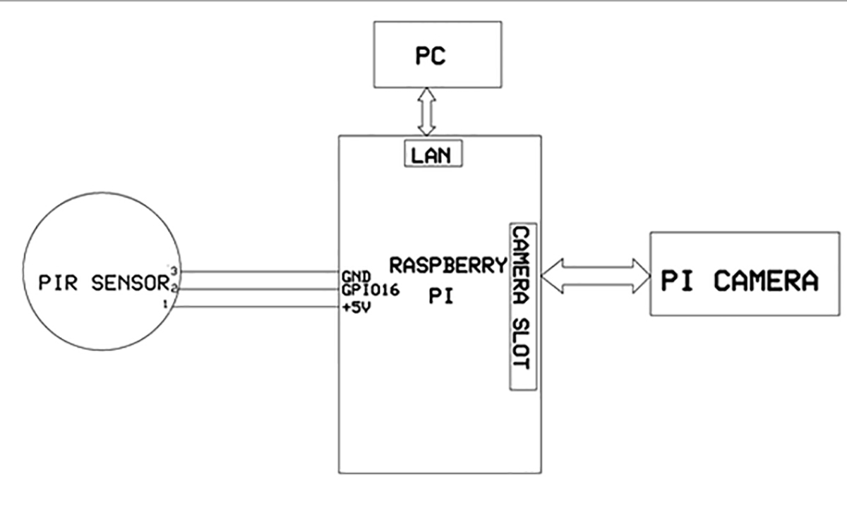
PIR is a sensor which is used to detect any motion. If any motion is detected by PIR sensor then it will send activation message to raspberry pi. Then raspberry pi will turn on the camera and then pi camera will capture the image.
Description:-
Block diagram:

Fig. 1: Block Diagram of Raspberry Pi based Intruder Alarm
Ethernet :

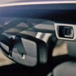
Fig. 2: Image showing Ethernet Cable connecting PC and Raspberry Pi
It is a Family of computer networking technologies for local area networks (LANs) and metropolitan area networks (MANs). It was commercially introduced in 1980 and first standardized in 1983 as IEEE 802.3, and has since been refined to support higher bit rates and longer link distances. Over time, Ethernet has largely replaced competing wired LAN technologies such as token ring, FDDI, and ARCNET. The primary alternative for contemporary LANs is not a wired standard, but instead a wireless LAN standardized as IEEE 802.11 and also known as Wi-Fi.
The Ethernet standards comprise several wiring and signaling variants of the OSI physical layer in use with Ethernet. The original 10BASE5 Ethernet used coaxial cable as a shared medium. Later the coaxial cables were replaced with twisted pair and fiber optic links in conjunction with hubs or switches. Over the course of its history, Ethernet data transfer rates have been increased from the original 3 megabits per second (Mbit/s) to the latest 100 gigabits per second (Gbit/s), with 400 Gbit/s expected by early 2017
Systems communicating over Ethernet divide a stream of data into shorter pieces called frames. Each frame contains source and destination addresses and error-checking data so that damaged data can be detected and re-transmitted. As per the OSI model, Ethernet provides services up to and including the data link layer.
PIR sensor:-

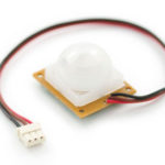
Fig. 3: Typical Image of PIR Sensor
An individual PIR sensor detects changes in the amount of infrared radiation impinging upon it, which varies depending on the temperature and surface characteristics of the objects in front of the sensor.] When an object, such as a human, passes in front of the background, such as a wall, the temperature at that point in the sensor’s field of view will rise from room temperature to body temperature, and then back again. The sensor converts the resulting change in the incoming infrared radiation into a change in the output voltage, and this triggers the detection. Moving objects of similar temperature to the background but different surface characteristics may also have a different infrared emission pattern, and thus sometimes trigger the detector.
PIRs come in many configurations for a wide variety of applications. The most common models have numerous Fresnel lenses or mirror segments, an effective range of about ten meters (thirty feet), and a field of view less than 180 degrees. Models with wider fields of view, including 360 degrees, are available—typically designed to mount on a ceiling. Some larger PIRs are made with single segment mirrors and can sense changes in infrared energy over one hundred feet away from the PIR. There are also PIRs designed with reversible orientation mirrors which allow either broad coverage (110° wide) or very narrow “curtain” coverage or with individually selectable segments to “shape” the coverage.
Raspberry pi:-

Fig. 4: Typical Image of Raspberry Pi 2
The Raspberry Pi is a series of credit card-sized single-board computers developed in the UK by the Raspberry Pi Foundation with the intention of promoting the teaching of basic computer science in schools.
The original Raspberry Pi is based on the Broadcom BCM2835 system on a chip (SoC), which includes an ARM1176JZF-S700 MHz processor, Video Core IV GPU, and was originally shipped with 256 megabytes of RAM, later upgraded (models B and B+) to 512 MB. The system has Secure Digital (SD) (models A and B) or Micro-SD (models A+ and B+) sockets for boot media and persistent storage. In 2014, the Raspberry Pi Foundation launched the Compute Module, which packages a BCM2835 with 512 MB RAM and MMC flash chip into a module for use as a part of embedded systems.
Pi camera:-

Fig. 5: Typical Image of Rapsberry Pi Camera
The Raspberry Pi Camera Module is a custom designed add-on for Raspberry Pi. It attaches to Raspberry Pi by way of one of the two small sockets on the board upper surface. This interface uses the dedicated CSI interface, which was designed especially for interfacing to cameras. The CSI bus is capable of extremely high data rates, and it exclusively carries pixel data.
The board itself is tiny, at around 25mm x 20mm x 9mm. It also weighs just over 3g, making it perfect for mobile or other applications where size and weight are important. It connects to Raspberry Pi by way of a short ribbon cable. The camera is connected to the BCM2835 processor on the Pi via the CSI bus, a higher bandwidth link which carries pixel data from the camera back to the processor. This bus travels along the ribbon cable that attaches the camera board to the Pi.the sensor itself has a native resolution of 5 megapixel, and has a fixed focus lens onboard. In terms of still images, the camera is capable of 2592 x 1944 pixel static images, and also supports 1080p30, 720p60 and 640x480p60/90 video.
Working of the circuit:-
After installing the OS in the Raspberry pi connect the raspberry pi to PC through LAN cable with the help of MobeXterm software we have to open the desktop of raspberry pi.
Before opening desktop open MobeXterm it consists of SSH click on SSH and give the IP address which IP address we have given in the installation of OS in raspberry pi and click on that IP address and open a new window and give the command lxsession for opening the desktop of raspberry pi.The desktop consists of so many apps like games ,python IDE and root terminal etc…open python IDE and write the code for our requirement and save it as pirsensor.py.open root terminal and for set the path give the command cd desktop and for execute the code give the command sudo python3 pirsensor.py if any motion is detected the PIR sensor is activated and it will give the activation to the raspberry pi and the raspberry pi turn on the camera and capture the images.
Number of components
· Raspberry pi model B+ board-1
· Pi camera-1
· PIR sensor-1
Pin number:-
Pin description of raspberry pi:-

Fig. 6: Pin Diagram of Raspberry Pi GPIO
Connect PIR sensor output as follows
PIR 1st pin supply (+5v) (pin2).
PIR 2nd pin output (GPIO16).
PIR 3rdpin ground (pin 9)
Supply voltage values:-
· Raspberry pi – 5v
· PIR sensor – 5v
Implemented circuit image:-

Fig. 7:
Prototype of Raspberry Pi based Intruder Alarm
You may also like:


Project Source Code
###
from time import sleep
import RPi.GPIO as GPIO
import picamera
from tkinter import *
from threading import Thread
def motion():
photo = PhotoImage(file="hero.gif")
w = Label(master, image=photo)
w.photo = photo
w.pack()
mainloop()
def threadings():
GPIO.setmode(GPIO.BCM)
GPIO.setup(16, GPIO.IN)
while True:
if ( GPIO.input(16) == True ):
print ("Warning - MOTION has been detected!")
with picamera.PiCamera() as camera:
camera.start_preview()
sleep(2)
camera.capture('/home/pi/Desktop/hero.gif')
camera.stop_preview()
master = Tk()
photo = PhotoImage(file="hero.gif")
w = Label(master, image=photo)
w.photo = photo
w.pack()
mainloop()
else:
print ("All is QUIET in RPi...")
sleep(1);
motion()
while True:
t=Thread(target=threadings)
t.start()
t.join()
###
Circuit Diagrams
Project Video
Filed Under: Electronic Projects
Filed Under: Electronic Projects

Questions related to this article?
👉Ask and discuss on Electro-Tech-Online.com and EDAboard.com forums.
Tell Us What You Think!!
You must be logged in to post a comment.