LoRa (“long-range”) is an excellent wireless communication solution without networking capabilities. It’s a reliable, energy-efficient, encryption-secured, low-cost wireless connectivity technology. And as its name suggests, it offers an extremely long range.
LoRa operates at the physical layer of an OSI model and is implemented at the chip level — excluding the network management protocol. This has become an advantage as system engineers can implement data link and network layer protocols over LoRa modulation and according to the requirements of a particular application.
In Europe, most of the LoRa networks are on build-it-yourself configurations. Aside from custom networks, the ideal networking solution for a LoRa network is LoRaWAN.
LoRaWAN is an open LPWAN protocol designed to operate on the LoRa modulation, adding data links and network layer protocols. The protocol is responsible for the configuration of end devices and the management of peer-to-peer data communication.
This article will discuss how devices are configured in a LoRa network and how LoRaWAN connects them and the internet. For an introduction to these technologies, first read What is LoRa and LoRaWAN?.

LoRaWAN network elements
There are five building blocks of a LoRaWAN network that are connected in a star-of-stars topology:
1. End devices are sensors, actuators, or both. They contain a chip for the LoRa RF modulation and communicate wirelessly using LoRa technology. Most are battery-operated as part of an IoT network, connecting with the LoRaWAN network through gateways. The end devices follow a random-access protocol, ALOHA, and can access the network through one or many nearby gateways within range.
2. Gateways are devices responsible for forwarding messages to and from end devices to a network server. The gateway has an IP backbone that’s cellular (3G/4G/5G), fiber optic, Ethernet, Wi-Fi, or 2.4GHz radio link, which connects to the server. Each gateway is registered with one LoRaWAN network server.
When an end device transmits an uplink message, it’s received by all nearby gateways within its range. The message is forwarded to the network server, where it’s singled out by de-duplication. This network architecture of the end devices and gateways ensures the accuracy of the uplink packet and serves as low-cost localization. When the gateway receives a downlink packet for delivery to an end device, the payload is passed without interruption.
The gateways operate at the physical layer of the OSI model and serve as LoRa RF message forwarders. Gateways are broadly classified into indoor and outdoor gateways. The eight or 16-channel indoor gateways have no antenna and, therefore, lower receiver sensitivity and range than the outdoor ones. Indoor gateways are ideal for multi-story buildings and deep-indoor locations.
The 64-channel outdoor gateways have high receiver sensitivity and great range. They’re typically connected to an antenna with a coaxial cable, so they’re ideal for outdoor cellular towers or high-rise buildings.
3. Network server is the server-side software for LoRa network management, managing data communication between the end devices (connected to the network server via gateways) and the application server. This server authenticates the end devices, de-duplicate uplink messages, encrypts uplink and downlink messages between end devices and application servers, and confirms the uplink messages.
Additionally, it’s responsible for device addressing within the LoRa network through ADR commands, routing downlink messages to end devices through the appropriate gateways. The network server is the only server that forwards join-request and join-accept messages between the end devices and the join server.
4. Application server is the server-side software responsible for running the main application and providing a cloud-based business solution. There can be several application servers connected to a network server each running a specific server-side application. The application servers receive application-specific uplink data messages from end devices via the network server, process application data, and return results as application-layer downlink payloads.
5. Join server is the server-side software responsible for processing join-request and join-accept messages between end devices and the application server. Join servers were introduced with LoRaWAN v.1.1 for the LoRa architecture to enable OTAA. The end devices require activation by means of network and application session keys. The join server processes join-request messages, generates application session keys, transfers network and application keys to the network server and the application server, and enables end-device activation.
The end devices connected to a LoRa network are activated in two ways, Activation by Personalization (ABP) and Over-The-Air Activation (OTAA). ABP provides hard-coding end devices with keys to configure and join a LoRa network. However, it has security issues and lacks capabilities for online updates.
LoRaWAN device classes
End devices have three types of LoRaWAN implementations (Class A, B, and C), called device classes. All LoRaWAN end devices have Class A implementation. They may or may not also have Class B or Class C implementations.
The three LoRaWAN implementations differ in the way device receives downlink payloads and the time it remains active.
Class A is implemented in all LoRaWAN end devices. The exclusively Class A devices are primarily in sleep modes and only communicate with the application server intermittently.
The device could send an uplink data message to the application server at anytime. After each uplink transmission, the device opens two short receive windows for the downlink payloads from the application server. The application server may transfer the downlink payload in the end device’s first receive or second receive window, but not both.
If the device cannot receive a downlink payload after an uplink transmission, another downlink is initiated after the next uplink. Class A LoRaWAN end devices are typically sensors for alarms, environmental monitoring, or location tracking.
Class B devices have a scheduled receive window for periodic downlink payloads from the application server. The devices are configured to open the receive windows in response to time-synchronized beacons from the network server. They also have Class A implementation and open two short receive windows after each uplink transmission.
Class B devices are intermittently active, so they have shorter battery life and lower latency than Class A devices. They’re often used for sensor data logging or reporting.
Class C devices have a continuously active receive window, enabling them to get downlink payloads without any latency. LoRaWAN devices have a half-duplex bidirectional data communication, so they cannot receive downlink payloads when transmitting uplink messages. They are mains powered and remain in active mode. Utility meters operating cut-off valves are one example of device use.
End device activation
There are two end-device activations in a LoRaWAN network, Activation By Personalization (ABP) and Over-The-Air Activation (OTAA). With LoRaWAN v1.1, OTAA is the preferred method of device activation. Device activation is a step-by-step procedure and is entirely managed by a join server in a LoRa network.
Message types
The messages communicated between end devices and the application server in a LoRa network contain application data and/or MAC commands. The LoraWAN has half-duplex bi-directional data communication between the network server and the end devices. The messages are classified based on data direction.
In terms of direction, they’re classified as follows.
- Uplink messages are transmitted by end devices for the join or application server. Messages sent to a join server typically contain MAC commands. Those communicated to the application server usually contain MAC commands and/or application data. Messages are received by the network server through multiple gateways and routed to a join or application server based on the MAC message type.
- Downlink messages are sent by the network server to end devices. The message is relayed through a single gateway by the network server to render it to an end device.
MAC message types
The messages in a LoRa network are routed by the network server according to the MAC message type. The following MAC message types are available in LoRaWAN 1.1 and LoRaWAN 1.0 specifications.
- Join-request: An uplink message by an end device for OTAA activation.
- Join-accept: A downlink message from a join server for the OTAA activation of an end device.
- Rejoin-request: An uplink message to rejoin the LoRA network from an end device. This message type is reserved in LoRaWAN v1.0 but available in LoRaWAN v1.1.
- Unconfirmed data up: An uplink data frame in which confirmation is not required.
- Unconfirmed data down: A downlink data frame in which confirmation is not required.
- Confirmed data up: An uplink data frame from the end device whereby confirmation (i.e. acknowledgement from the network server) is requested.
- Confirmed data down: A downlink data frame from the network server whereby confirmation is requested.
- Proprietary: A non-standard proprietary message.
LoRaWAN security
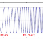
LoraWAN radio link is reliable because of chirp modulation. Aside for the FSK-like modulation, the LoRaWAN architecture is designed to ensure messages are delivered with the utmost accuracy.
Uplink messages are communicated to multiple gateways and de-duplicated at the network server, leaving no chance for data corruption. The network communication is secured with 128-bit security keys, including NwkSKey, AppSKey, and AppKey. The algorithm AES-128 is used to encrypt messages, which is similar to the encryption in WiFi standard IEEE 802.15.4. With OTAA activation, there’s essentially no possibility of device hacking or man-in-the-middle attacks.
For unique identification of the end devices by the application server, an application key AppKey is shared only between the application server and end devices. There may also be a default application key used for the activation of multiple devices or custom application keys generated per end device. This key is used to generate the network and application session keys.
As soon as an end device joins the LoRa network, the network server generates two security keys: the network session key (NwkSKey) and the application session key (AppSKey). These session keys are applicable only during a single session.
The network session key is shared and used to authenticate the end device within the network server. The key maps non-unique device addresses to 64-bit Extended Unique Identifiers DevEUI and AppEUI. Only the authorized end device can join the LoRa network because of the network session key. The Message Integrity Code (MIC) uses the same key, which serves as a checksum to validate message integrity.
The application session key encrypts and decrypts downlink payloads between the end devices and the application server. This key is private and never shared within the network, so only the authorized end device can transmit or receive messages with the application server.
In OTAA activation, both session keys generate a unique per-device session. In ABP activation, the keys are regenerated only when explicitly changed.
The data security is further manifolded by using frame counters. There are frame counters for both uplink and downlink messages. When an end device is activated, both frame counters are set to 0. When an uplink message is transmitted, the respective frame counter is updated.
Similarly, the downlink frame counter is immediately updated when an end device receives a downlink payload. The end devices and the application server ignore any message containing a frame counter value lower than the updated frame counters.
You may also like:


Filed Under: IoT applications, What Is

Questions related to this article?
👉Ask and discuss on EDAboard.com and Electro-Tech-Online.com forums.
Tell Us What You Think!!
You must be logged in to post a comment.