In digital systems, any information is represented by binary codes. There are many binary code systems as mentioned in the first tutorial of this series. A binary code of n bits can represent 2n discrete symbols or elements of coded information. The digital circuits that perform encoding of digital information are called encoders while digital circuits that decode the coded digital information are called decoders. An encoder with enable pins is called multiplexer while a decoder with enable pins is called demultiplexer.
The encoder, decoder, multiplexer as well as demultiplexer are combinational logic circuits as their output at any time depends upon the combination of the input signals present at that instant only and does not depend on any past conditions. Let us learn about each in this tutorial.
Decoders –
The decoders are used to decode binary information in a digital system. The input lines to a decoder are used to feed binary data while based on the binary data, one of the output lines is selected which represents the respective minterm. If a decoder has n input lines then, it can have maximum 2n output lines. With n number of input lines, the decoder can decode n-bit digital data. Like with 3 input lines, a decoder can decode 3-bit binary data and so maximum 23 or 8 binary symbols. If there are some unused combinations in n-bit coded information, the decoder can have fewer than 2n output lines. So, any decoder is n-to-m line decoder where m <= 2n.
In a decoder, each output line represents a minterm which is selected based on the input binary data. For any input data only one output line is activated at a time. It can be noted that in a decoder, the number of output lines is always greater than number of input lines. If the number of inputs and outputs in a decoder circuit are equal, it is then called converter.
The decoders are usually constructed using AND or NAND Gates. The output of an AND gate is only HIGH when all the inputs are HIGH. So, AND gate is the basic decoding element in a decoder circuit. For example, in a 4-to-16-line decoder, the digital circuit used in decoding the binary code 1001 will be as follow –

Fig. 1: Decoding Circuit Built using AND Gate
In the decoding element (of the 4-to-16-line decoder) shown above, to make all the inputs of the AND gate HIGH, the two middle bits must be inverted by using two NOT gates. So, when the input binary data will be 1001, the only output line connected to the above decoding circuit will be activated and set HIGH.
For simplicity let us take 2-to-4-line decoder as an example. A 2-to-4-line decoder has two input line (say A and B). With 2 inputs, 4 binary codes can be represented, so there can be 4 output lines (say D0, D1, D2 and D3). Each output line represents a minterm like D0 represents A’B’, D1 represents A’B, D2 represents AB’ and D3 represents AB. A 2-to-4-line decoder can be represented by the following block diagram –

Fig. 2: 2-to-4-Line Decoder Block Diagram
It will have the following truth table –

From the above truth table, the digital circuit for 2-to-4-line decoder can be constructed using AND gates and NOT gates as follow –

Fig. 3: 2-to-4-Line Decoder Circuit Diagram
If a decoder is constructed using NAND gates, then the respective output line is set LOW instead of HIGH for a binary code. For example, the digital circuit for 2-to-4-line decoder constructed using NAND gates will be as follow –

Fig. 4: 2-to-4-Line Decoder Circuit NAND Implementation
The decoders are used in many applications like data demultiplexing, digital display, digital to analog converters, memory addressing etc.
De-Multiplexers –
De-Multiplexers are digital circuits that are used to transmit binary data from one line to many. The word “demultiplexer” itself means one into many. So, Demultiplexing is the process of taking information from one input and transmitting the same over one of several outputs. The demultiplexers have digital circuit similar to decoders except that they have a single input line and have select lines to determine the output line for data transmission. The data is transmitted over a single output line at a time. Like decoder, if a de-multiplexer has n select lines, there can be 2n or less output lines controlled by them in a demultiplexer. A de-multiplexer can be represented by the following block diagram –

Fig. 5: Demultiplexer Block Diagram
It can be noted that a demultiplexer has one input signal, m select signals and n output signals where n <= 2m. The select inputs determine that to which output line the data input will be connected. With the help of a demultiplexer, serial data is converted to parallel data.
For example, in a 1-to-4-line demultiplexer, there is a single input (say D), four outputs (say Y0 to Y3) and two select lines (say S1 and S2). The truth table of the 1-to-4-line demultiplexer is as follow –

From the truth table, it can be noted that the data input is connected to output Y0 when S1 = 0 and S0 = 0. The data input is connected to output Y1 when S1 = 0 and S0 = 1. The data input is connected to output Y2 when S1 = 1 and S0 = 0. The data input is connected to output Y3 when S1 = 1 and S0 = 1. A demultiplexer can be constructed using AND gates and NOT gates like the decoder circuits. From the above truth table, the digital circuit for 1-to-4-line demultiplexer is as follow –
Fig. 6: 4-Output Demultiplexer Circuit Diagram
So, the 1-to-4-line demultiplexer can be implemented using four 3 – input AND gates and two NOT gates. The input data line is connected to all the AND gates. The two select lines S1 and S0 enable only one gate at a time and the data that appears on the input line passes through the selected gate to the associated output line.
The demultiplexers are used in communication systems, computers chips for connecting ALU with registers and in serial to parallel converters.
Encoders –
The encoders are used for coding binary data. They are opposite to decoders. So, they perform inverse operation of a decoder. The opposite of the decoding process is called encoding. The encoder is a combinational logic circuit that converts an active input signal into a coded output signal.
It has n input lines, only one of which is active at any time and m output lines. It encodes one of the active inputs to a coded binary output with m bits. In an encoder, the number of output lines is less than the number of inputs. If an encoder has n input lines and m output lines than n<= 2m. An encoder can be represented by the following block diagram –

Fig. 7: Encoder Block Diagram
For example, let us consider Priority Encoder. It is a special type of encoder in which priority is given to the input lines. If two or more input lines is HIGH at the same time, then the input line with highest priority is considered. In a 4-to-2-line priority encoder, there are four inputs say D0, D1, D2 and D3 and two outputs say Y0 and Y1. Out of the four inputs D3 has the highest priority and D0 has the lowest priority. That means if D3 = 1 then Y1 Y0 will be equal to 11 irrespective of the other inputs. Similarly if D3 = 0 and D2 = 1 then Y1 Y0 will be equal to 10 irrespective of the other inputs. A 4-to-2-line priority encoder can be represented by the following block diagram –
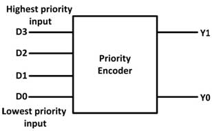
Fig. 8: 4-Input Priority Encoder Block Diagram
It has the following truth table –
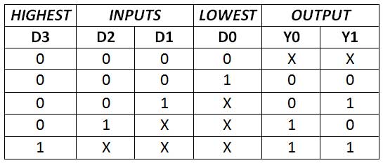
An encoder can be constructed using AND, OR and NOT gates. From the above truth table, the digital logic circuit for 4-to-2-line encoder can designed as follow –

Fig. 9: 4-Input Priority Encoder Circuit Diagram
Multiplexers –
The multiplexers are used for routing digital data from many to one line. They convert parallel data into serial data. The term multiplex itself means many to one. Multiplexing is the process of transmitting a large number of information over a single line.
A digital multiplexer is a combinational circuit that selects single digital information from several resources and transmits the selected information on a single output line. A multiplexer is also called a data selector, where it selects one of many inputs and sends the information to the output. The multiplexers are similar to encoders except that they have several data – input lines and a single output line. The selection of a particular input line is controlled by a set of select lines. A multiplexer can be represented by the following block diagram –

Fig. 10: Multiplexer Block Diagram
It can be noted that a multiplexer has n input lines, m select signals and one output line where n <= 2m. The selection line decides the number of input lines of a particular multiplexer. If the number of the n input lines is equal to 2m, then m select lines are required to select one of n input lines. For example, to select one out of 4 input lines, two select lines are required and to select one out of 8 input lines, 3 select lines are required.
Like in a four inputs multiplexer, there has four data input lines (say D0 to D3), single out line (say Y) and two select lines (say S0 and S1) to select one of the four input lines. A 4-input multiplexer can be represented by the following block diagram –

Fig. 11: 4-Input Multiplexer Block Diagram
It has the following truth table –

A multiplexer circuit is similar to encoder circuit. Like encoders, the multiplexers can be constructed using AND, OR and NOT gates. From the above truth table, the logic gate diagram for 4-input multiplexer is as follow –
Fig. 12: 4-Input Multiplexer Circuit Diagram
From the logic circuit, it can be seen that when S1S0 equal to 00 is applied to select lines, the two input to the AND gate associated with D0 is equal to 1 and third input is connected to D0 Data. The other 3 AND gates have 0 in at least one of their inputs, so that their outputs will be equal to 0. Hence the OR output Y will be equal to D0. When S1S0 equal to 01 is applied to select lines, the Data on the input D1 appears on the data output line. Similarly, when S1S0 equal to 10 is applied to select lines, the Data on the input D2 appears on the data output line. When S1S0 equal to 11 is applied to select lines, the Data on the input D3 appears on the data output line.
The multiplexers are used in telephony, communication systems and computer memories. They are also used as parallel to serial data converters.
In the next tutorial, learn to design encoder and decoder circuits using 7400 Series Logic Gate ICs.
Filed Under: Articles
Log in to leave a comment:
Lost your password?
Don't have an account? Register here