Many RF receivers can be connected to a common RF transmitter by matching the address byte. When all the receiver modules have a common address byte, the address byte of RF transmitter can be hard-wired to sync with all the receivers at once. But, there may be a situation where different RF receivers having different address bytes may need to get data from a single RF transmitter. In such a case, the address byte of the transmitter module needs to be changed either manually using tactile switches at the address pins of the transmitter’s encoder chip or controlling the address byte by interfacing the address pins of the transmitter’s encoder chip to a microcontroller’s GPIO pins. In this project an RF transmitter is configured to send data to three RF receiver sections having different address bytes. The address byte of the RF transmitter is changed by an Arduino board which alters the address byte based on human input through a three-switch keypad. A separate four-switch keypad is used to modify the data that has to be transmitted.
The three receiver sections have different operations performed. At first receiver, LEDs are switched ON or OFF based on data bits status of received nibble from the transmitter. At second receiver section, a relay connected to D0 bit of decoder is operated based on the bit status over data transmission. In third RF receiver section, two servomotors are rotated based on the transmitted data.
Components Required
| Sr. No. | Components Required | Quantity Required |
|---|---|---|
| 1 | RF Transmitter Module(434Mhz) | 1 |
| 2 | RF Transmitter Module(434 Mhz) | 3 |
| 3 | HT12E encoder IC | 1 |
| 4 | HT12E Encoder IC | 3 |
| 5 | LED | 4 |
| 6 | Resistor – 1MΩ (Quarter Watt) | 1 |
| 7 | Resistor – 50K | 3 |
| 8 | Resitor – 10K | 11 |
| 9 | Resistor network 8×1-1K | 3 |
| 10 | Battery – 9V | 4 |
| 11 | Breadboard | 4 |
| 12 | Switches(Push button) | 7 |
| 13 | Servos | 2 |
| 14 | Arduino Pro mini | 2 |
| 15 | Relay | 1 |
| 16 | Bulb | 1 |
| 17 | Connecting wires | – |

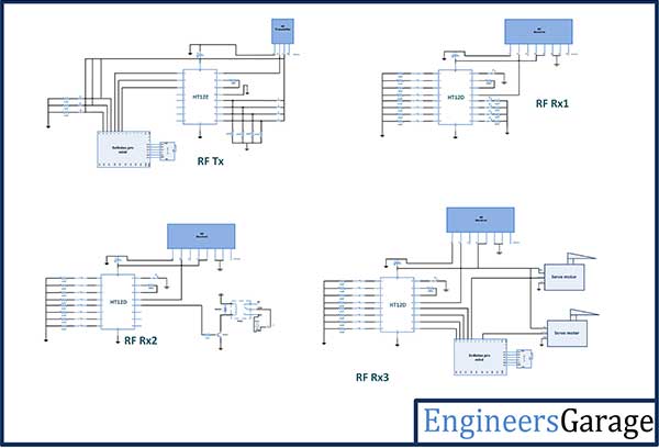
BLOCK DIAGRAM
Circuit Connections
There are four circuits involved in this projects – :
1) Transmitter Section – The circuit connections of the transmitter section are made as specified by the data sheets of RF transmitter and HT12E encoder IC. There is a modification in the circuit configuration of the transmitter section. The last five bits A3 to A7 of the address pins of the encoder IC are hard-wired to ground but first 3 bits A0 to A2 of the address pins of the encoder IC are connected to pins 9 down to 7 of the transmitter side Arduino Pro Mini. By default, the transmitter has an address of 0x00 but it can be altered between 0x00 and 0x07 by changing the digital output at the Arduino pins. The pin 14 of the encoder IC is connected to ground to enable uninterrupted transmission of the radio signal. The antenna of 17.25 cm height is used at pin 4 of the RF transmitter to boast operational range of the module. Learn more about increasing operational range of RF module by using antenna and increasing the transmission power. At pins 12 down to 10 of the Arduino, three tactile switches are connected which dominates the modification of the address byte of RF transmitter. A four switch keypad made from tactile switches is connected to data pins of HT12E encoder IC. The data pins of encoder IC by default are connected to ground (corresponding to LOW logic) but gets VCC (corresponding to HIGH logic) through the tactile switches.

2) Receiver Section 1 – At the receiver section 1, there is a connection of RF receiver with the antenna and HT12D decoder IC. These connections are made as specified by the data sheets of the RF receiver and the decoder IC. The decoder IC is configured to have an address of 0x01. A series of LEDs is connected at the data bits D0 to D3 of the decoder through a pull up resistor to the ground. Therefore, when a HIGH logic is passed to respective data bit, the respective LED must get forward biased and start glowing.
3) Receiver Section 2 – At the receiver section 2, RF receiver is connected to a relay. The circuit connections of the RF receiver and HT12D decoder IC are as specified by their data sheets. A relay is connected at D0 data pin of the decoder IC which operates a bulb ON and OFF.
4) Receiver Section 3 – At receiver section 3, the RF receiver circuit is connected to an Arduino Pro Mini which controls two servo motors. The circuit connections of RF receiver and HT12D IC are again made according to their data sheets. The data pins of the decoder IC are connected to pin 13 down to 10 of the Arduino boards. The control terminals of the servos are connected to pin 6 and 9 of the Arduino board. The servos receive supply and ground from the same battery which powers the Arduino board.
How the Circuit Works
At the transmitter section, the address byte of the HT12E encoder is logically controlled by Arduino board and data to be transmitted is manually feed with the help of tactile switches connected at data pins of the encoder IC. The first three address bits of the encoder IC are logically controlled by the microcontroller, hence RF transmitter can tune to 8 different address bytes.
| SW1 | SW2 | SW3 | A1 | A2 | A3 | A4 | A5 | A6 | A7 | A8 |
| 0 | 0 | 0 | 1 | 0 | 0 | 0 | 0 | 0 | 0 | 0 |
| 0 | 0 | 1 | 0 | 1 | 0 | 0 | 0 | 0 | 0 | 0 |
| 0 | 1 | 0 | 0 | 0 | 1 | 0 | 0 | 0 | 0 | 0 |
| 0 | 1 | 1 | 0 | 0 | 0 | 1 | 0 | 0 | 0 | 0 |
| 1 | 0 | 0 | 0 | 0 | 0 | 0 | 1 | 0 | 0 | 0 |
| 1 | 0 | 1 | 0 | 0 | 0 | 0 | 0 | 1 | 0 | 0 |
| 1 | 1 | 0 | 0 | 0 | 0 | 0 | 0 | 0 | 1 | 0 |
| 1 | 1 | 1 | 0 | 0 | 0 | 0 | 0 | 0 | 0 | 1 |
In the project, only three receiver sections having different addresses are connecting with the transmitter section. Therefore, the transmitter section has to tune to only three address bytes apart from 0x00 which is the default address byte and connects to none of the receiver sections. The decoder IC at receiver section 1, 2 and 3 are configured to fixed address bytes of 0x01, 0x02 and 0x04 respectively. The transmitter section can tune to receiver sections 1, 2 and 3 by tipping the A0, A1 and A2 address bit of the encoder to HIGH logic. The A0, A1 and A2 address bits connected to pins 9 down to 7 of Arduino goes to HIGH logic when a HIGH logic is input at pins 12 down to 10 of the Arduino respectively. The embedded code at the transmitter side Arduino manages to alter address pin statuses according to the address control switch’s configuration.

The transmitter section connects to the receiver section 1 when switch connected to pin 12 is pressed corresponding to which a HIGH logic is out from pin 9 of the Arduino and A0 gets HIGH. The data transmitted is controlled by the switches connected at data pins of encoder IC. When a switch is pressed the data pin gets the VCC and a HIGH logic is transmitted corresponding to that data bit. The same data is reflected at the data pins of decoder IC. When a HIGH signal is received at a data pin of the decoder IC, current starts flowing through the LED which is connected to the pin with a pull-up resistor of 10K ohm in series to the ground. Thus the LED starts glowing on receiving a HIGH bit at the respective data pin of the decoder IC. If the respective switch at the data pin of encoder IC is pressed off, the corresponding data bit at the encoder is again set to LOW and a LOW bit is received at the respective data bit of the decoder IC. Thereof, the LED connected to the respective data pin of the decoder IC is again switched to off.
The transmitter section connects to the receiver section 2 when switch connected to pin 11 is pressed corresponding to which a HIGH logic is out from pin 8 of the Arduino and A1 gets HIGH. The receiver section 2 has only a relay connected to D0 pin of decoder IC. Therefore if switch connected to D0 pin of encoder IC is pressed down, a HIGH logic is transmitted on D0 and same is reflected at the D0 bit of the decoder. On receiving a HIGH logic at D0, the transistor circuit has a current flow between base and emitter and the relay remains switched OFF and so the bulb. if switch connected to D0 pin of encoder IC is released, a LOW logic is transmitted on D0 and same is reflected at the D0 bit of the decoder. On receiving a LOW logic at D0, the transistor circuit has a current flow between collector and emitter and the relay gets switched ON and the bulb starts glowing.
The transmitter section connects to the receiver section 3 when switch connected to pin 10 is pressed corresponding to which a HIGH logic is out from pin 7 of the Arduino and A2 gets HIGH. The data transmitted is reflected at the data pins of decoder IC and is read as parallel data by the Arduino board. The section 3 Arduino has program code to check status of each data bit and generate servo output accordingly. The rotation of servos can be between angles 0 degree and 180 degrees. Check out the receiver section 3 Arduino code to learn how data at pins are parallel read and used to control servos.
Programming Guide
Transmitter Section
The embedded program runs on the Arduino board. When the board is powered on, the program executes continuously in a loop. First the program code imports and loads the required standard libraries Wire.h for configuring digital I/O pins. The pins connected to switches are referenced by A<address bit denomination>In and pins connected to address pins of encoder IC are referenced by A<address bit denomination>Out.
#include <Wire.h>
A setup() function is called, inside which, pins mapped to data pins of encoder are set to digital output while pin connected to switches are set to digital input by using pinMode() function. The pins interfaced with encoder pins are set to HIGH by default using the digitalWrite() function. The baud rate of the Arduino board is set to 9600 bits per second using Serial.begin() function.
A loop() function is called where pins connected to switches have their status read by digitalRead() function and status of each switch is checked using an if-else-if logic.
If A0In is HIGH, the A0Out is set to HIGH using digitalWrite() function.
If A1In is HIGH, the A1Out is set to HIGH using digitalWrite() function.
If A2In is HIGH, the A2Out is set to HIGH using digitalWrite() function.
This ends the transmitter side Arduino code.
Receiver Section 1 and 2 –
No programmable chip is used in receiver section 1 and 2 hence no program code is needed for these sections. The circuits at section 1 and 2 operates directly based on the digital logic received at the data pins of the decoder ICs.
Receiver Section 3 –
On the receiver section 3 Arduino, the program code first imports the required standard libraries. The Servo.h is included to implement the servo interfacing and two servo objects are declared. The pins connected to data pins of decoder IC are referenced to D<denomination> names.
A setup() function is called where baud rate of the Arduino is set to 9600 bits per second. The servo connected pins are mapped to respective servo objects using the attach() function on servo objects while pins interfaced to data pins of decoder IC are set digital input using the pinMode() function.
A loop() function is called where the status of data pins is read and relevant angle is passed to the write function of servo objects.
Project Source Code
Project Source Code
###
#include <Wire.h> int A0In = 12; int A0Out = 9; int A1In = 11; int A1Out = 8; int A2In = 10; int A2Out = 7; void setup(){ pinMode(A0In, INPUT); pinMode(A0Out, OUTPUT); pinMode(A1In, INPUT); pinMode(A1Out, OUTPUT); pinMode(A2In, INPUT); pinMode(A2Out, OUTPUT);digitalWrite(A0Out, HIGH); digitalWrite(A1Out, HIGH); digitalWrite(A2Out, HIGH); Serial.begin(9600); delay(1000); }void loop(){ // reading switch status. int A0In = digitalRead(A0In); int A1In = digitalRead(A1In); int A2In = digitalRead(A2In); digitalWrite(A0Out, HIGH); digitalWrite(A1Out, HIGH); digitalWrite(A2Out, HIGH);if (A0In == HIGH && A1In ==LOW && A2In == LOW ) { digitalWrite(A0Out,HIGH); delay(1000); } if (A0In == LOW && A1In == HIGH && A2In == LOW) { digitalWrite(A1Out,HIGH); delay(1000); } if (A0In == LOW && A1In == LOW && A2In == HIGH) { digitalWrite(A2Out,HIGH); delay(1000); }#include <Servo.h> Servo servo; Servo myservo; int D0 = 13; int D1 = 12; int D2 = 11; int D3 = 10; void setup() { Serial.begin(9600); servo.attach(9);myservo.attach(10); pinMode(D0, INPUT); pinMode(D1, INPUT); pinMode(D2, INPUT); pinMode(D3, INPUT); }void loop(){ int D0 = digitalRead(D0); int D1 = digitalRead(D1); int D2 = digitalRead(D2); int D3 = digitalRead(D3); if (D0 == HIGH){ servo.write(35); } else if (D1 == HIGH){ servo.write(145); } else if (D2 == HIGH){ myservo.write(110); } else if (D3 == HIGH){ myservo.write(150); }else if (D0 == HIGH && D1 == HIGH){ servo.write(90); }else if (D1 == HIGH && D2 == HIGH){ myservo.write(90); } }###
Circuit Diagrams
Filed Under: Electronic Projects

Questions related to this article?
👉Ask and discuss on EDAboard.com and Electro-Tech-Online.com forums.
Tell Us What You Think!!
You must be logged in to post a comment.