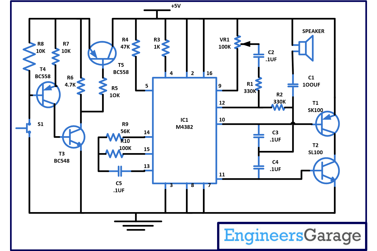
This circuit describe here will generate different sounds when your guest presses the door bell . This circuit is based on a melody generator IC M3482 which can generate 12 different kinds of songs. M3482 is a mask ROM and has inbuilt multi instrument melody generator. This IC is implemented using CMOS technology and designed to play songs according to the previously programmed information. M3482 IC can be operated with just 1.5V power supply and also have very low stand by current which lead to longer battery life. And it also have on chip envelop modulator and pre amplifier. This IC can also be used in different application like in toys, music box, timer and telephones circuits for producing different tones.
[[wysiwyg_imageupload:9960:]]
Fig. 1: Prototype of Multitone Generator Circuit on Breadboard
To understand the working first have a look on the pin configuration of IC
1. Pin 1 is known as TSP – In normal operation this pin is left open.
2. Pin 2 is known as CE – To enable the IC it is connected to power supply and to disable the chip it is connected to ground.
3. Pin 3 known as LP – Only one song is played if connected to supply and all song play if connected to ground.
4. Pin 4 known as SL – On every positive going edge it will change the song.
5. Pin 5 known as AS – If you want to repeat the song connect it to power supply otherwise connect it to ground.
6.Pin 6 is known as NC – Means no connection.
7. Pin 7 known as ENV – This pin should be grounded.
8. Pin 8 known as ground.
9. Pin 9 known as MTO – Used as modulated tone digital output.
10. Pin 10 and 11 are known as OP1 and OP2 – Used as preamplifier for output.
11. Pin 12 known as MT1 – Used to provide modulated input signal to pre amplifier.
12. Pin 14, pin 15 and 13 known as OSC2 and OSC1 – Use as external oscillator.
13. Pin 16 is for power supply.
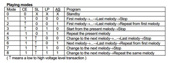
So from above you can now connect the pin according to your requirement means you want to play all songs or one song, or you want to stop at any song or you want to repeat any song. You can also use below table to select the pin configuration –

Fig. 2: Pin Configuration Of IC
Circuit Diagrams
Project Components
Filed Under: Electronic Projects


Questions related to this article?
👉Ask and discuss on Electro-Tech-Online.com and EDAboard.com forums.
Tell Us What You Think!!
You must be logged in to post a comment.