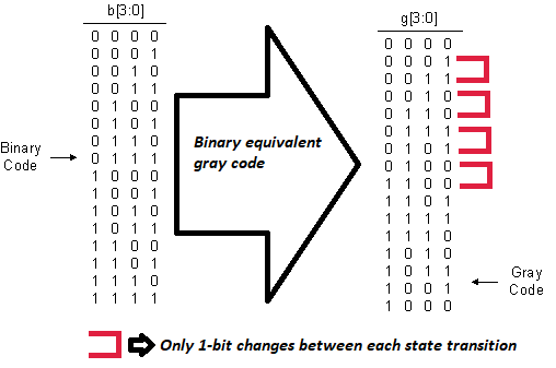
Binary to gray code state transition
|
Why N-bit gray counter
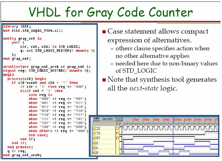
Gray code logic design in vhdl
Vhdl gray counter code
In the main entity first a generic N: integer:=6 is defined. The generic variable is used to declare the size of the gray counter. In my case i want a 6-bit gray counter so i initialized it with 6. You can change it according to your need. Clock, reset and enable signals are input to the entity and the only output is our gray code. Notice that the output port size is dependent on the generic variable N. clock, reset and enable are 1-bit inputs.
In the architecture part few signals are defined. These signals are used to hold the values manipulated for gray counter by finite state machine. The reset is synchronous which means that reset execute on positive edge of the clock. In the absence of clock you cant reset the system.
Coming to the main and complex logic. How the gray counter is incremented in vhdl case?
After reset the current state value is 000000. We then xor this current state with the 5 lsb(least significant bits) of current state while concatenating the 0 at msb(most significant bit) of current state. & is concatenating operator. The result is placed in hold variable hold <= Currstate XOR (‘0’ & hold(N-1 DOWNTO 1));.
In the next statement we increment the hold by 1. The result is placed in next_hold variable next_hold <= std_logic_vector(unsigned(hold) + 1);.
In the third statement we perform the same concatenation and logical xor but this time on next_hold variable. The result is placed in Nextstate variable Nextstate <= next_hold XOR (‘0’ & next_hold(N-1 DOWNTO 1)); .
The current state is assigned to the output and next state is calculated. This next state is transferred to current state on next rising edge of clock.
Important: The above logic is hard to explain. But i bet you if you try to write them on paper and do the logic xor manually you can easily understand whats going on in.
6-bit gray counter main entity is shown below. The internal circuit is composed of xor gates flip flops and other components. The figure of internal components is huge and its not possible to show it in single picture so i removed it.
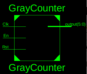
6-bit Gray Counter in vhdl
|
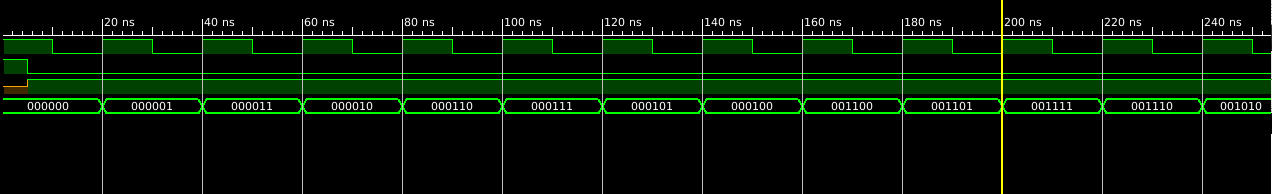
VHDL test bench
Filed Under: Microcontroller Projects, VHDL
Log in to leave a comment:
Lost your password?
Don't have an account? Register here