Obstacle avoidance is one of the most important aspects of mobile robotics. Without it robot movement would be very restrictive and fragile.
Obstacle Avoiding is a task which is used for detecting the objects placed in the path of your robot or any vehicle. So, to protect robot from any physical damages.
An obstacle avoiding robot is an intelligent device, which can automatically sense and overcome obstacles on its path. It is developed without micro-controller in order to eliminate critical circuits, difficult programming etc. All you want to do is to just understand the circuit diagram and start doing this robot. This simple technique can be incorporated in wheeled robots to keep them away from damages and accidents.
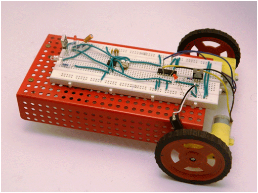
Fig. 1: Prototype of Microcontroller-Less Obstacle Avoiding Robot
Obstacle Avoidance is a robotic discipline with the objective of moving vehicles on the basis of the sensorial information. The use of these methods front to classic methods (path planning) is a natural alternative when the scenario is dynamic with an unpredictable behavior. In these cases, the surroundings do not remain invariable, and thus the sensory information is used to detect the changes consequently adapting moving.
Block Diagram
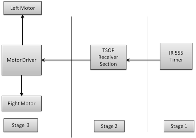
Fig. 2: Block Diagram of 555 IC based Obstacle Avoiding Robot
Explanation of block diagram
IR module are used to avoid the obstacle if obstacle comes on the front of the IR module. Here 555 timer IC are used to generate the IR signal and TSOP (thin small outline package) are used to receive the IR signal.
Stage 1
Stage 1
IR 555 Timer Section
555 is a very commonly used IC for generating accurate timing pulses. It is an 8 pin timer IC and has mainly two modes of operation monostable and astable. In monostable mode time delay of the pulses can be precisely controlled by an external resistor and a capacitor whereas in astable mode the frequency & duty cycle are controlled by two external resistors and a capacitor. 555 timer is very commonly used for generating time delays and pulses.
Pin Diagram of LM555 IC
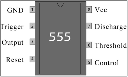
Fig. 3: Pin Diagram of NE555 IC
Pin Description:
|
Pin No |
Function |
Name |
|
1 |
Ground (0V) |
Ground |
|
2 |
Voltage below 1/3 Vcc to trigger the pulse |
Trigger |
|
3 |
Pulsating output |
Output |
|
4 |
Active low; interrupts the timing interval at Output |
Reset |
|
5 |
Provides access to the internal voltage divider; default 2/3 Vcc |
Control Voltage |
|
6 |
The pulse ends when the voltage is greater than Control |
Threshold |
|
7 |
Open collector output; to discharge the capacitor |
Discharge |
|
8 |
Supply voltage; 5V (4.5V – 16 V) |
Vcc |
LEDs are used as indicator lamps in many devices and are increasingly used for general lighting.
Long leg is positive.
Short leg is negative.
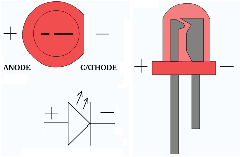
Fig. 4: Pin Diagram of LED
IR Led:
An infrared light-emitting diode (LED) is a type of electronic device that emits infrared light not visible to the naked eye. An infrared LED operates like a regular LED, but may use different materials to produce infrared light.

Fig. 5: Typical Image of IR LED
Stage 2
Stage 2
TSOP Receiver Section
TSOP receiver section are used to receive the IR radiation coming from the IR led. TSOP have three pin as given in the below diagram.
TSOP Receiver section
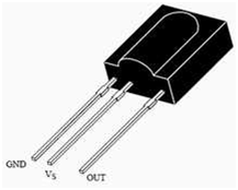
Fig. 6: Pin Diagram of TSOP IR Receiver
|
Sr.No |
Pin No |
Pin Name |
|
1 |
Pin 1 |
Gnd |
|
2 |
Pin 2 |
Vs |
|
3 |
Pin 3 |
out |
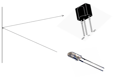
Fig. 7: Image showing working principle of TSOP IR Receiver
How to IR sensor work
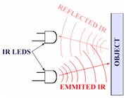
Fig. 8: Image showing working principle of IR Sensor
It is the same principle in ALL Infra-Red proximity sensors. The basic idea is to send infra red light through IR-LEDs, which is then reflected by any object in front of the sensor.
One of the most useful sensor find its application while detecting object/hurdles, edges of surface etc. With a long range of 20 cm, TLL interface and ambient light protection makes it easy and reliable to use.
Features:
· Range: 20 cm
Motor Driving Stage
In this stage the motor driver l293D IC is used for to drive the motor. As the signal comes from the inverter IC it drives the motor according to signals comes.
L293D IC
L293D is a dual H-bridge motor driver integrated circuit (IC). Motor drivers act as current amplifiers since they take a low-current control signal and provide a higher-current signal. This higher current signal is used to drive the motors.
L293D contains two inbuilt H-bridge driver circuits. In its common mode of operation, two DC motors can be driven simultaneously, both in forward and reverse direction. The motor operations of two motors can be controlled by input logic at pins 2 & 7 and 10 & 15. Input logic 00 or 11 will stop the corresponding motor. Logic 01 and 10 will rotate it in clockwise and anticlockwise directions, respectively.
Enable pins 1 and 9 (corresponding to the two motors) must be high for motors to start operating. When an enable input is high, the associated driver gets enabled. As a result, the outputs become active and work in phase with their inputs. Similarly, when the enable input is low, that driver is disabled, and their outputs are off and in the high-impedance state.
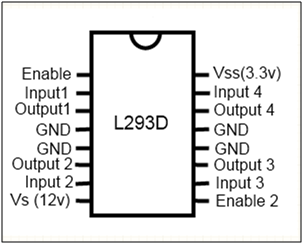
Fig. 9: Pin Diagram of L293D Motor Driver IC
Truth table for robot Movement
|
Sr.No |
IN1 |
IN2 |
IN3 |
IN4 |
Movement of robot |
|
1 |
1 |
0 |
0 |
1 |
Forward |
|
2 |
1 |
1 |
1 |
1 |
Stop |
|
3 |
1 |
0 |
1 |
0 |
Left |
|
4 |
0 |
1 |
0 |
1 |
Right |
Accessories Required to make obstacle avoiding robot
|
Sr.No. |
Component Name |
Quantity |
|
1. |
Double AA batteries cell holder |
1 |
|
2. |
Chassis ( Robotic Platform) |
1 |
|
3 |
Breadboard |
1 |
|
4 |
Nipper |
1 |
|
5. |
Stripper |
1 |
|
6. |
One core wire |
As per the use |
|
7. |
Nose pliers |
1 |
|
8 |
Screw driver |
1 |
Making the Robotic Chassis
Mechanical Assembly of robotic chassis
Step 1:
Take a robotic chassis.
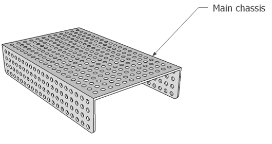
Fig. 10: Representational Image of Main Chassis of Robot
Step 2:
Take the BO motor as shown in the diagram.
Step 3:
Take a M2.5 (25) screw to fit the BO motor on the chassis. Fit the motor in upward direction as shown in the figure. Here the last hole of the chassis are used to fit the motor.
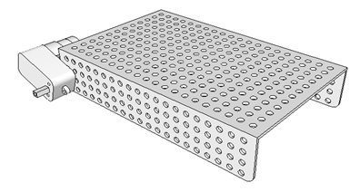
Fig. 11: Image showing motor attachment to robot’s chassis
Note
Here kept the motor screw M2.5 (25) in the separate polyethene and also don’t mix it with other screw.
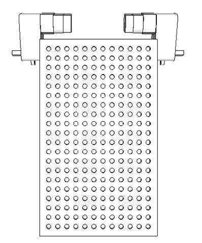
Fig. 12: Image showing motor attachment on both sides of robot’s chassis
Step 4
Fit the both wheel on the both motor shaft as shown in figure. Fix the motor with self tapping red wheel screw.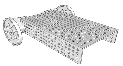
Fig. 13: Image showing attachment of wheels to motors on robot’
Step 5
Take the caster wheel and caster wheel strip as shown in the diagram.
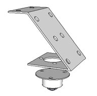
Fig. 14: Representational Image of Caster Wheel and Strip for Robot
Step 6
Inset three M3 -10 screw into the caster wheel. Now fit the caster wheel into the caster wheel strip in the outward direction as shown in the figure.
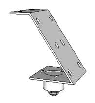
Fig. 15: Image showing attachment of Caster Wheel to Strip for Robot
Step 7
Now fit the caster wheel strip on the middle position of the chassis as shown in the diagram by using two M3-10 screw.
Now your robotic platform is ready to be used.
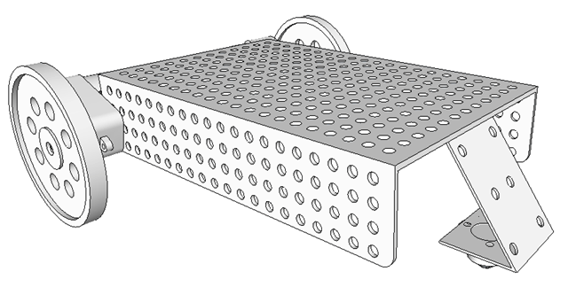
Fig. 16: Image showing attachment of Caster Wheel strip to Chassis of Robot
Breadboard Connections
Breadboard Connection
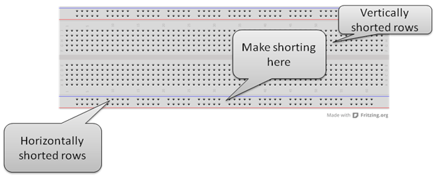
Fig. 17: Image showing rows and columns on a Breadboard
Breadboard Connection
· Give positive +5 volt supply in first row.
· Connect the GND in the second row of the breadboard.
· Connect + 5 volt upper row with the below row to make below line +5 volt .
· Connect the upper gnd line with the lower gnd line to make the below row gnd line.
· Short the below middle rows as connect the +5 volt to +5volt line and gnd line with the gnd line.
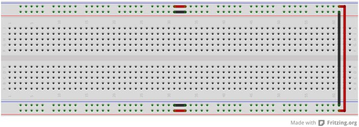
Fig. 18: Typical image of Breadboard
Construction of obstacle avoiding robot on breadboard
· Power Supply
· Motor Driver
· IR sensor module ( Comparator + Line sensor plate)
· Inverter IC section
Power Supply Section
Power Supply
General Description
Power supply is used for to give power to the whole circuit assembly. The below component are used for to make power supply section.
Component list for power supply
|
Sr.No. |
Component Name |
Component list |
|
1 |
DC jack |
1 |
|
2 |
7805 voltage regulator IC |
1 |
|
3 |
3 mm Led |
1 |
|
4 |
Resistor (220 ? ) (Red, Red, Black, Black ) |
1 |
Explanation of component
Make the below connection for power supply as given in below image.
DC jack
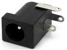
Fig. 19: Typical Image of DC Jack
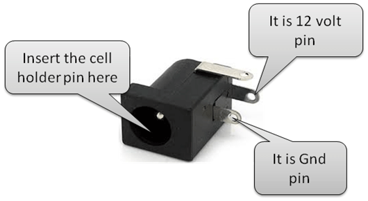
Fig. 20: Pin Diagram of DC Jack
7805 Connection pin diagram
|
Sr .No |
7805 Pin No |
7805 Pin name |
|
1 |
Pin 1 |
+12 volt (Given by battery) |
|
2 |
Pin 2 |
Gnd |
|
3 |
Pin3 |
+ 5 (output to give whole circuit ) |
By referring below images you can make the power supply circuit.
1. Breadboard Image
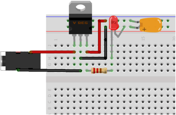
Fig. 21: Representational Image of Power Supply Circuit on Breadboard
2. Schematic Diagram for power supply
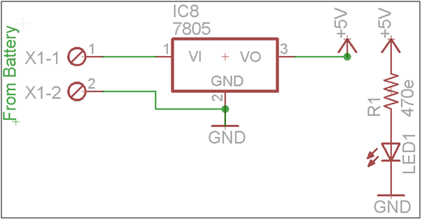
Fig. 22: Circuit Diagram of Power Supply for Robot
Testing of power Supply Section
If the led will be glow it means the power supply circuit connection is correct. and now you can able to give power to whole the assembly.
Motor Driver Section
Motor driver section
eneral Description
Now you have make a motor driver section which is used for to drive the motor. Here to drive the motor you have use L293D IC.
Component List for Motor Driver Section
|
Sr No |
Component Name |
|
1. |
L29D3 IC Section |
|
2. |
One core wire |
Designing of motor driver section
By referring below images and table you can make and test the motor driver section.
L293D pin connection
|
Sr.No |
L293 D pin |
Supply voltage |
|
1 |
Pin no 1 |
+5 volt |
|
2 |
Pin no 9 |
+5 volt |
|
3 |
Pin no 16 |
+5 volt |
|
4 |
Pin no 8 |
+12 volt |
|
5 |
Pin no 4 & 5 |
Gnd |
|
6 |
Pin no 12 & 13 |
Gnd |
Connection of Motor with L293D IC
|
Sr. No. |
Output pins |
Motor Wire |
|
1 |
o/p1 |
First wire of first motor |
|
2 |
o/p2 |
Second wire of first motor |
|
3 |
o/p3 |
First wire of second motor |
|
4 |
o/p4 |
Second wire of second motor |
Breadboard Image
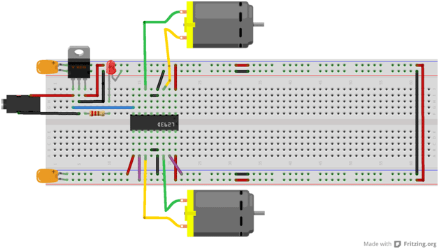
Fig. 23: Representational Image of Motor Driver Circuit on Breadboard
Schematic image of motor driver section
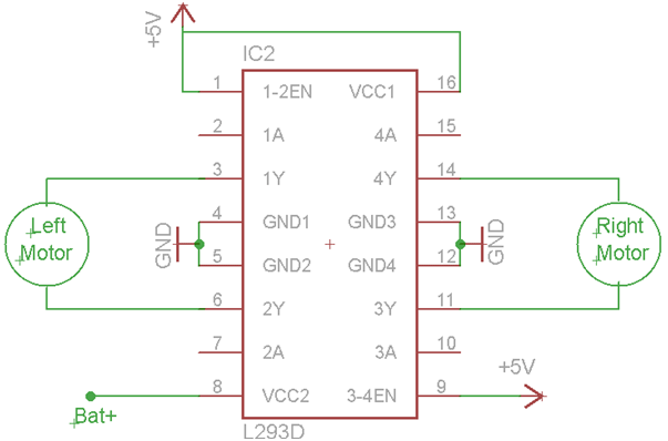
Fig. 24: Circuit Diagram of L293D IC based Motor Driver
Give the below supply at input terminal of L293d IC to test the motor
|
Sr.No. |
Pins Name |
Given supply |
|
1 |
In1 |
+5 |
|
2 |
In2 |
Gnd |
|
3 |
In3 |
+5 |
|
4 |
In4 |
Gnd |
Note
· Short 4 (gnd) and 5 (gnd) pin with the jumper. Jumper can be taken from the wire.
· In the same way also short pin no 12 (gnd) and 13(gnd) of the l293D IC.
Testing of motor driver section

Fig. 25: Representational Image of Motor Driver Circuit on a Breadboard
Step 1
Connect one wire of first motor with the o/p1 pin of L293D IC. And second one is with second o/p2 of L293D IC.
The motor should be rotate in clockwise direction from your front side. If the motor rotate in anticlockwise direction than make it in clockwise direction by exchanging it’s wire with L293 o/p pins.
Filed Under: Electronic Projects


Questions related to this article?
👉Ask and discuss on Electro-Tech-Online.com and EDAboard.com forums.
Tell Us What You Think!!
You must be logged in to post a comment.