Why a PCB?
This tutorial will help you to understand the necessity of the PCB. Here, I have described the evolution of PCB in different steps. Connecting a circuit without any soldering gun or breadboard is a complex process. I tried to connect an amplifier circuit with a transistor, four resistors, and three capacitors, which you can see in the video. Connecting electronics components directly using wire, is referred as a “discrete circuit”.

Fig. 1: Image of a Simple LED Circuit
In the above image, it can be seen that a single lead wire 5mm LED and 1K resistor are connected to two 1.5V Duracell batteries. This is a small and simple example for discrete circuit. In order to explain the concept in detail, I am choosing another simple circuit, an RC amplifier circuit.
In the image given below, we can see the RC amplifier circuit with one transistor, four resistors, and three capacitors.

Fig. 2: Image of a Circuit Diagram Drawn on Paper
I am selecting components as, one BC558 transistor, two 1k resistors, one 10K resistor, one 330ohms resistors, two 0.1uF capacitors, and one 10uF electrolytic capacitor. Here, I have tried to connect these components directly with their leads and wires. After finishing the circuit it looks similar to the image given below.

Fig. 3: Image of Components Placed on Circuit Diagram
We can also connect the circuit with wires so as to make it look less clumsy. Besides, the following shortfalls can be observed in the circuit:
1. Although the circuit works, it looks clumsy.
2. It has a lot of loose connections, so output may fluctuate.
3. Enough possibilities of short circuit. So, it is not safe and hence precautions are needed.
4. Reliability is very low.
5. Physical strength of the circuit is very low.
To avoid clumsiness in circuit connections, we need to fix the components on a plane or on any surface. After that we can connect the circuit by using wires.
Here I have tried to fix these components on a thin paper. To avoid clumsiness in circuit, I drew the components positions properly. Have a look at the figure given below.
Fig. 4: Image of Component Icons Drawn on a Paper
After fixing the components on the paper and finishing the circuit, I found out that it looks good but only from the top. If we turn the paper, bottom side components leads again look very untidy. But it does not matter, as everything will be clear after connecting the circuit. However, it is still incomplete because by using this method, I have solved just the clumsiness of the circuit. But remaining problems are still there.
Now let’s move on and fix the remaining problems as well. To start with, I connected the circuit on a thick card board to impart some physical strength to the circuit. For this, I drew component positions on board and made holes to place them. After fixing these components, I connected leads at bottom side of the board. At this stage, the board looks similar to the figure given below:

Fig. 5: Image of a PCB with Soldered Components

Fig. 6: Image showing Soldering of Components on a PCB
After finishing circuit on cardboard, we can observe that the loose connections have been fixed. However, there is still the issue of short circuit that needs to be taken care of.
So, in order to avoid loose connections and short circuit possibilities completely, I went on to connect and solder these points using wires. Please see in the figure given below.

Fig. 7: Image showing Soldering of Components on a PCB with Wires
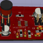
Although it seems to be better than the previous one, yet it is just a wired board and not a printed circuit board. So, to resolve the issue, we can print all these wire connections on this board. Just look at the figure given below of a printed circuit board with all components and connections.

Fig. 8: Image of a Commercial PCB
This is how it looks! Hence we use PCB i.e. Printed Circuit Board to keep the circuit simple and reliable.
Here is the video
You may also like:


Filed Under: Featured Contributions, Tutorials

Questions related to this article?
👉Ask and discuss on EDAboard.com and Electro-Tech-Online.com forums.
Tell Us What You Think!!
You must be logged in to post a comment.