Engineers Garage

  • Projects and Tutorials
    • Electronic Projects
      • 8051
      • Arduino
      • ARM
      • AVR
      • PIC
      • Raspberry pi
      • STM32
    • Tutorials
    • Circuit Design
    • Project Videos
    • Components
  • Articles
    • Tech Articles
    • Insight
    • Invention Stories
    • How to
    • What Is
  • News
    • Electronic Products News
    • DIY Reviews
    • Guest Post
  • Forums
    • EDABoard.com
    • Electro-Tech-Online
    • EG Forum Archive
  • Digi-Key Store
    • Cables, Wires
    • Connectors, Interconnect
    • Discrete
    • Electromechanical
    • Embedded Computers
    • Enclosures, Hardware, Office
    • Integrated Circuits (ICs)
    • Isolators
    • LED/Optoelectronics
    • Passive
    • Power, Circuit Protection
    • Programmers
    • RF, Wireless
    • Semiconductors
    • Sensors, Transducers
    • Test Products
    • Tools
  • EE Resources
    • DesignFast
    • LEAP Awards
    • Oscilloscope Product Finder
    • White Papers
    • Webinars
  • EE Learning Center
    • Design Guides
      • WiFi & the IOT Design Guide
      • Microcontrollers Design Guide
      • State of the Art Inductors Design Guide
  • Women in Engineering

PIR Sensor based Alarm using transistor and UM3561 IC

By Ashutosh Bhatt


This Passive InfraRed Alarm system (PIR alarm) can switch on a Lamp or Alarm when it detects the heat from an object like moving person. The name PIR (Passive Infrared) is given to the sensor because it receives the infrared rays passively and do not emit any infrared ray. The lamp or alarm remains on few minutes depending on the mono time setting of the PIR Sensor used. Ready to fix PIR Sensors are available with Fresnel lens to increase sensitivity and to filter ambient light. Its range is around 5 meters at 45 degree cone angle.  

Passive Infrared
Human beings cannot detect infrared rays but emits infrared from the body as heat like all other warm blooded animals (animals in which body temperature remains constant- Mammals and Birds)).This is exploited in Motion detectors to detect the presence of human beings. PIR sensors (Passive InfraRed sensor) are used to activate an alarm system using the Infrared in the form of body heat from the human body. PIR sensor is an electronic device that measures the infrared in its field of view. Movement is detected by the sensor when an infrared source like human passes in front of the sensor with one temperature and comparing another temperature like that of the wall in which the sensor is mounted.
About PIR Sensor
The PIR sensor is mounted on a PCB with other semiconductors. The complete assembly is mounted in a case with a Fresnel lens molded in front of it. Behind the lens, there is a small window through which infrared enters into the sensor. The window is covered with a transparent plastic which allows only IR rays to enter into the sensor and preventsvisible light. The filtering window limits the IR rays to 8-14 micrometers similar to the IR rays from human body.
 

PIR Sensor

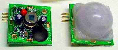
Fig. 1: Image Showing PIR Sensor

The PIR sensor is a solid state device made of ¼ inch pyroelectric material as a thin film. The pyroelectric material may be Gallium nitride (GaN), Cesium nitrate(CsNO3), Cobalt phthalocyanine, Lithium tantalite (LiTaO3) etc. They show both piezoelectric and pyroelectric properties. The sensor is made as part of the integrated circuit having 1 – 4 pixels of pyroelectric material. The paired pixels are connected to the inputs of a differential amplifier. The differential amplifier cancel each other the PIR measurements and the average temperature in the field of view is removed from the electrical signal. So that the IR energy on the sensor will not trigger the alarm. This prevents false triggering when exposed to flashes of light. The differential amplifier also minimizes the common mode interference from electric fields.The circuit in the PIR sensor can be connected to a relay switch and the sensor resets at power on and remains standby.
Circuits operation
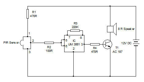
The PIR Sensor module is a pre assembled board with circuits to compare the infrared rays from the object and that of the nearby area like the mounting wall. When a person enters within the range of the Sensor, The Fresnel lens focus the IR energy into the sensor which had previously sensed the cooler area. This change in energy level makes the sensor warmer and makes a hot spot in it. The Module then gives around 3 volts( Check the output. In some makes, output is active low) .The high output saturates T1 and it conducts. When T1 conducts, T2 also conducts to drive the relay. The AC lamp or Alarm can be connected through the Common and NO contacts of the relay switch. When the person moves, the hot spot also moves which causes the electronic circuit to deactivate the relay. If the person tries to mask the sensor with some shield, the sensor develops a cold spot which also activate the alarm. Thus the PIR sensor is fail proof. 

PIR Sensor Module

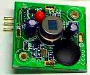
Fig. 2: Image of Circuit of PIR Sensor

The circuit can be powered using 12 volt regulated power supply or battery.
Mounting of PIR Sensor
Fixing and focusing the PIR sensor is important to give maximum sensitivity and to prevent false alarms. Mounting the device on the wall at an angle of 45 degree and 2-3 meters height will give good results. The sensor may saturate if strong sunlight andhead light from vehicles fall on the sensor. Such positions should be avoided.


Circuit Diagrams

pir-sensor-based-alarm_0
pir-sensor-based-um3561-ala_0


Filed Under: Electronic Projects


Questions related to this article?
👉Ask and discuss on EDAboard.com and Electro-Tech-Online.com forums.


Tell Us What You Think!! Cancel reply

You must be logged in to post a comment.

HAVE A QUESTION?

Have a technical question about an article or other engineering questions? Check out our engineering forums EDABoard.com and Electro-Tech-Online.com where you can get those questions asked and answered by your peers!


Featured Tutorials

  • PS2 Keyboard To Store Text In SD Card Using Arduino Circuit Setup On Breadboard
    How To Use PS2 Keyboard To Store Text In SD Card Using Arduino- (Part 42/49)
  • Wireless Path Tracking System Using Mouse, XBee And Arduino Circuit Setup On Breadboard
    How To Make A Wireless Path Tracking System Using Mouse, XBee And Arduino- (Part 43/49)
  • How to Make a Wireless Keyboard Using Xbee with Arduino- (Part 44/49)
  • Making Phone Call From GSM Module Using Arduino Circuit Setup On Breadboard
    How to Make Phonecall From GSM Module Using Arduino- (Part 45/49)
  • How to Make a Call using Keyboard, GSM Module and Arduino
    How To Make A Call Using Keyboard, GSM Module And Arduino- (Part 46/49)
  • Receiving SMS Using GSM Module With Arduino Prototype
    How to Receive SMS Using GSM Module with Arduino- (Part 47/49)

Stay Up To Date

Newsletter Signup

Sign up and receive our weekly newsletter for latest Tech articles, Electronics Projects, Tutorial series and other insightful tech content.

EE Training Center Classrooms

EE Classrooms

Recent Articles

  • Renesas delivers intelligent sensor solutions for IoT applications
  • Microchip Technology releases AVR-IoT Cellular Mini Development Board
  • Qualcomm acquires Cellwize to accelerate 5G adoption and spur infrastructure innovation
  • MediaTek’s chipset offers high-performance option for 5G smartphones
  • Nexperia’s new level translators support legacy and future mobile SIM cards

Most Popular

5G 555 timer circuit 8051 ai Arduino atmega16 automotive avr bluetooth dc motor display Electronic Part Electronic Parts Fujitsu ic infineontechnologies integratedcircuit Intel IoT ir lcd led maximintegratedproducts microchip microchiptechnology Microchip Technology microcontroller microcontrollers mosfet motor powermanagement Raspberry Pi remote renesaselectronics renesaselectronicscorporation Research samsung semiconductor sensor software STMicroelectronics switch Technology vishayintertechnology wireless

RSS EDABOARD.com Discussions

  • Co-simulation setup in HFSS
  • How do we test an antenna for its receiver capability?
  • highest frequency capture with arduino input capture
  • Limits of duty cycle for ICM7555 IC?
  • Help identifying drop in ssignal

RSS Electro-Tech-Online.com Discussions

  • ICM7555 IC duty cycle limit at high frequency?
  • writing totals in Eprom
  • undefined reference header file in proteus
  • How to test phone socket?
  • intro to PI
Engineers Garage
  • Analog IC TIps
  • Connector Tips
  • DesignFast
  • EDABoard Forums
  • EE World Online
  • Electro-Tech-Online Forums
  • Microcontroller Tips
  • Power Electronic Tips
  • Sensor Tips
  • Test and Measurement Tips
  • 5G Technology World
  • About Us
  • Contact Us
  • Advertise

Copyright © 2022 WTWH Media LLC. All Rights Reserved. The material on this site may not be reproduced, distributed, transmitted, cached or otherwise used, except with the prior written permission of WTWH Media
Privacy Policy | Advertising | About Us

Search Engineers Garage

  • Projects and Tutorials
    • Electronic Projects
      • 8051
      • Arduino
      • ARM
      • AVR
      • PIC
      • Raspberry pi
      • STM32
    • Tutorials
    • Circuit Design
    • Project Videos
    • Components
  • Articles
    • Tech Articles
    • Insight
    • Invention Stories
    • How to
    • What Is
  • News
    • Electronic Products News
    • DIY Reviews
    • Guest Post
  • Forums
    • EDABoard.com
    • Electro-Tech-Online
    • EG Forum Archive
  • Digi-Key Store
    • Cables, Wires
    • Connectors, Interconnect
    • Discrete
    • Electromechanical
    • Embedded Computers
    • Enclosures, Hardware, Office
    • Integrated Circuits (ICs)
    • Isolators
    • LED/Optoelectronics
    • Passive
    • Power, Circuit Protection
    • Programmers
    • RF, Wireless
    • Semiconductors
    • Sensors, Transducers
    • Test Products
    • Tools
  • EE Resources
    • DesignFast
    • LEAP Awards
    • Oscilloscope Product Finder
    • White Papers
    • Webinars
  • EE Learning Center
    • Design Guides
      • WiFi & the IOT Design Guide
      • Microcontrollers Design Guide
      • State of the Art Inductors Design Guide
  • Women in Engineering