Power Failure Indicator in NRF24LE1
Nowadays most of our devices are portable and run on batteries. We often do not know when the battery is about to get discharged. Many systems have the battery voltage display to indicate the battery voltage but what if we don’t have the display in our system. In such a case, using a small LED to indicate low battery is very helpful for users to know about the battery status.
In this article, we are going to discuss a very important feature of NR24LE1 which enables power failure indicator.

Fig. 1: Prototype of NRF24LE1 based Power Failure Indicator
The NRF module comes with an inbuilt comparator known as Power-Failure (POF) Comparator. This comparator gives the MCU (Microcontroller Unit) an early warning of power failure. The comparator compares VDD (Supply voltage) and threshold voltage. It gives a warning when the VDD voltage falls below a threshold level. We know that the threshold level is a voltage level that can be set by user as per requirement. There are four threshold levels offered by NRF module: 2.1, 2.3, 2.4 and 2.5V.
The register through which we can access the functionality is POFCON (Power Failure Control) register. It’s an 8-bit register. Functions of various bits of the register are given below :
• Bit 7 – enable/disable POF comparator. 0:disable, 1:enable
• Bit 6:5 – set threshold level. 00 : 2.1V, 01 : 2.3V, 10 : 2.5V, 11 : 2.7V
• Bit 4 – warning. 0 : VDD above threshold, 1: VDD below threshold

| FUNCTION | INPUT PARAMETER | OUTPUT | DESCRIPTION |
|---|---|---|---|
| hal_pof_enable() | 0/1 | – | To enable the POF
0:Disable 1:Enable |
| hal_pof_set_threshold() | HAL_POF_THRESHOLD_2_1V
HAL_POF_THRESHOLD_2_3V HAL_POF_THRESHOLD_2_5V HAL_POF_THRESHOLD_2_7V |
– | To set threshold level:
2.1V, 2.3V, 2.5V, or 2.7V |
| hal_pof_warning() | – | 0/1 | To check POF warning
0 – No warning 1 – Warning |

Project Source Code
###

#include"reg24le1.h" // I/O header file for NRF24LE1

// main function

void main()

{

POFCON |= 0xe0; // POF enable with threshold at 2.7V

P0DIR = 0; // set PORT0 as output

P0 = 1; // Port 0 high


// infinite loop

while(1)

{

if(POFCON & 0x10) // check for warning

P00 = 0; // make Pin 0 of Port 0 low

}


}

###
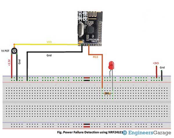
Circuit Diagrams
Project Video
Filed Under: Power, Tutorials
Filed Under: Power, Tutorials

Questions related to this article?
👉Ask and discuss on EDAboard.com and Electro-Tech-Online.com forums.
Tell Us What You Think!!
You must be logged in to post a comment.