Introduction:
DC motor is an actuator, which is used in many applications; especially in robotics it has huge applications. If we are operating dc motor with a switch just for on and off, it’s a simple technique but even though it has enormous use in embedded system. For example simple hand held fan with simple small dc motor, propeller and switch. But if dc motor attached to movable object then we can’t control it every time by following (running after) it. For example wheel based robots. We can start the robot just by switching it ON but to stop it again we have to run after it (assumption is funny but it is true). So, there are limitations because of wired control. To overcome the limitations and to improve application we are introducing wireless RF communication based dc motor control system.
In this project we can learn how to control a dc motor wirelessly. Wireless control of dc motor means switching it ON and OFF, and changing its direction of rotation wirelessly.
Description:
Dc motor has a two terminals, as explained in working logic of motor one terminal should be high (+Ve or Vcc or on logic 1) and another should be low (-Ve or Gnd or on logic 0), if we apply +ve on either side then there is a chance of motor damage. The dc motor speed of rotations depends on applied voltage. If 100 RPM @ 12 V dc motor is given only 6V then motor rotations are only 50 per minute. When we are controlling DC motor using Microcontroller we need a current amplifier between MC and motor, because MC output current is very less (in terms of few mA) but dc motor requires more than 600 mA.
While developing this project be careful in motor driver circuit. If 12 volts is applied in wrong pin of l293d, it may burn. Use isolators like opto-couplers at inputs of the l293d to isolate MC section from motor driver section.
In this project HT12E based transmitter wirelessly controls DC motor through HT12D receiver and motor driving chip L293D. so let us see how it is done. First, collect all the required components and other equipments as per given list.
Required components and other equipments:
Sr. no. Name of component Required qut
1 RF Tx module(434Mhz) 1
2 RF Rx module(434Mhz) 1
3 HT12E 1
4 HT12D 1
5 LED 1
6 Resistor – 1KΩ (Quarter watt) 8
7 Resistor – 1MΩ (Quarter watt) 1
8 Resistor – 50KΩ (Quarter watt) 1
9 Pushbutton 4
10 DC motors 2
11 Battery – 9V 1
12 Battery – 12V 1
13 L293D 1
14 Opto-coupler(MCT12E827Q) 4
15 Bread board 2
16 8×1 DIP switches 2
17 Resistor network 8×1@1K 2
18 connecting wires —
Circuit diagram:
Now step by step start building the circuit as per above circuit diagram
Procedure:
Transmitter section:
Step1: connect the four push buttons to the data input pins (10,11,12,13) of HT12E, with pull down resistors of 1 K.
Step2: connect 1MΩ resistor between 15 and 16 pins of HT12E.
Step3: connect 17 pin to the 2nd pin of RF transmitter, and 14 pin connect to the ground.
Step4: 1-8 pins of HT12E are address pins, all are connected to ground through 8×1 DIP switch with pull down resistor network (8×1@1KΩ). Pin 18 is connected to Vcc and pin 9 is connected to ground.
Step5: Connect RF Tx module’s pin 1 to the ground, pin 3 to the Vcc and pin 4 to the antenna.
Receiver section:
Step1: connect the decoder HT12D data out pins (10,11,12,13) to 1st pin of each opto-coupler separately.
Step1: connect 5th pin of each opto-coupler to Vcc and 2nd pin to the ground.
Step1: connect 4th pin of each opto-coupler to the L293D motor driver input pins (2,7,10,15).
Step2: connect pins 3, 4, 12 & 13 of L293D to ground and enable pins (1 & 9) to Vcc (+5V). Pin 16 is also connected to Vcc as it provides power supply to chip.
Step3: connect output pins 3 & 6 of L293D to motor 1 and other two output pins 11 & 14 to motor 2. To drive motor with 12V supply, connect the +Ve of 12V battery to the 8th pin of L293D and –Ve with ground.
Step4 : connect 50KΩ resistor between decoder 15 and 16 pins of HT12D.
Step5: connect 14 pin of decoder to the 2nd pin of RF transmitter, and 17 pin connect to the LED indicator (it will glow when signal is received)
Step6: 1-8 pins of HT12D are address pins, all are connected to ground through 8×1 DIP switch with pull down resistor network (8×1@1KΩ). Connect pin 18 to Vcc and pin 9 to ground.
Step7: Connect RF Rx module’s 1, 6, 7 pins to the ground, pins 4 & 5 to the Vcc and pin 8 to the antenna.
After building the circuit, now its time to see the working of circuit
Working:
1. The HT12E encoder inputs are controlled by switches, this parallel data converted by encoder into serial data and fed to transmitter input pin 2 from the 17th pin of encoder.
2. Transmitted data is ASK modulated signal. The data present in variations of the amplitude. The receiver within the range can receive the ASK signal and generates serial data same as at transmitter and fed to 14th pin of decoder (HT12D).
3. This serial data is converted in to parallel data by the decoder and the parallel data is available as output to pins 10, 11, 12 and 13.
4. These data output pins are connected to input of motor drive chip L293D through opto couplers
5. Motor driver L293D has two H-bridge circuits inside, each one controls one DC motor. L293D has two supply pins pin 16 and pin 8. 16th pin is for IC voltage supply and 8th pin is for motors power supply.
6. The decoder pins 10 and 11 controls the motor 1. When 10 – 11 pins are in the logic combination of 00, the motor is OFF. If pins logic combination is 01 then motor rotates in clock wise direction and if logic combination is 10 then motor rotates in anti clock wise direction.
7. Same for motor 2 that is connected with pin 12 and pin 13 of HT12D (through opto-couplers).
8. When we are applying sufficient voltage at 8th pin of L293D, DC motors rotate at full speed (RPM) as per motor specification. Or else based on voltage applied, RPM of dc motor changes.
Pictures:


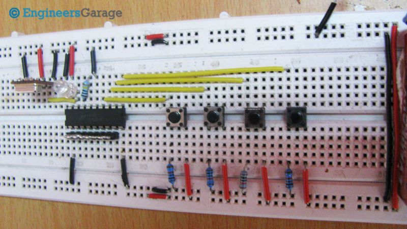

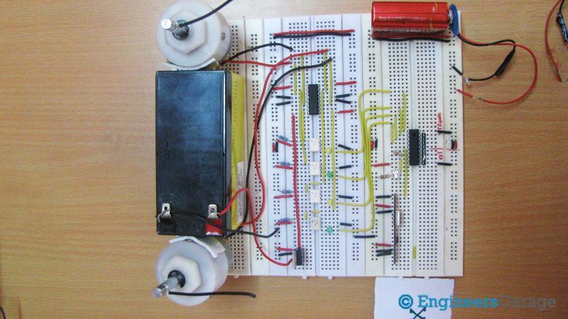


Following are some of the precautions that should be taken while running the circuit.
Precautions:
1. Address lines should be same at both transmitter and receiver side.
2. At transmitter 14th pin of HT12E should be connect to ground or connect a switch between ground and the 14th pin to reset the encoder.
3. At transmitter side resistor between 15 and 16 pins of HT12E should be between 750MΩ to 1MΩ and at receiver side resistor between 15 and 16 pins of HT12D should be between 30KΩ to 50KΩ.
4. Incase if you want to use any other battery please check the data sheets of HT12E/HT12D before.
5. When connecting L293D take care about power and ground pin connections.
6. Apply 12V at 8th pin of L293D.
Project Source Code
Project Source Code
###
//Program to###
Circuit Diagrams

Filed Under: Electronic Projects

Questions related to this article?
👉Ask and discuss on EDAboard.com and Electro-Tech-Online.com forums.
Tell Us What You Think!!
You must be logged in to post a comment.