Engineers Garage

  • Electronic Projects & Tutorials
    • Electronic Projects
      • Arduino Projects
      • AVR
      • Raspberry pi
      • ESP8266
      • BeagleBone
      • 8051 Microcontroller
      • ARM
      • PIC Microcontroller
      • STM32
    • Tutorials
      • Audio Electronics
      • Battery Management
      • Brainwave
      • Electric Vehicles
      • EMI/EMC/RFI
      • Hardware Filters
      • IoT tutorials
      • Power Tutorials
      • Python
      • Sensors
      • USB
      • VHDL
    • Circuit Design
    • Project Videos
    • Components
  • Articles
    • Tech Articles
    • Insight
    • Invention Stories
    • How to
    • What Is
  • News
    • Electronic Product News
    • Business News
    • Company/Start-up News
    • DIY Reviews
    • Guest Post
  • Forums
    • EDABoard.com
    • Electro-Tech-Online
    • EG Forum Archive
  • DigiKey Store
    • Cables, Wires
    • Connectors, Interconnect
    • Discrete
    • Electromechanical
    • Embedded Computers
    • Enclosures, Hardware, Office
    • Integrated Circuits (ICs)
    • Isolators
    • LED/Optoelectronics
    • Passive
    • Power, Circuit Protection
    • Programmers
    • RF, Wireless
    • Semiconductors
    • Sensors, Transducers
    • Test Products
    • Tools
  • Learn
    • eBooks/Tech Tips
    • Design Guides
    • Learning Center
    • Tech Toolboxes
    • Webinars & Digital Events
  • Resources
    • Digital Issues
    • EE Training Days
    • LEAP Awards
    • Podcasts
    • Webinars / Digital Events
    • White Papers
    • Engineering Diversity & Inclusion
    • DesignFast
  • Guest Post Guidelines
  • Advertise
  • Subscribe

Testing Bluetooth AT Commands

By Venu Gopal September 21, 2023

Bluetooth is a popular wireless technology standard designed for data exchange over short distances. Bluetooth is so common that it’s now the part of smartphones and comes in lots of embedded devices. Many wearable devices also use Bluetooth to pair with their accessories or co-devices. The Bluetooth interface uses UHF Radio wave in ISM band from 2.4 GHz to 2.485 GHz. It was invented by telecom vendor Ericsson in 1994 and developed by Bluetooth Special Interest Group. A Bluetooth connection has a range from 10 M to 100 M.
Making embedded devices Bluetooth enabled is a popular trend. The HC-05 Bluetooth Module is a commonly used and widely available Bluetooth module that can be added to an embedded project to make it Bluetooth enabled. The module can work as both Master and the Slave. The module connects with a microcontroller through serial communication. It is basically a 2.4 GHz Radio Transceiver with V 2.0+ Enhanced data rate of 3 Mbps modulation. The module can operate in two modes –
1. Automatic Connection Work Mode
2. Order Response Work Mode
In automatic work mode module can work in either of the three roles – Master, slave, and Loopback. In this mode, module follows default way to establish connection and exchange data. In Order response mode the user can set control parameters by sending AT commands. To enter into the AT mode, the 34th pin of the module needs to be connected to the power supply.
The modules have six commonly used pins apart from which there are programmable input/output pins and pins for communication over UART, SPI, USB and Synchronous PCM. The 34th pin is a programmable input/output pin which is designated as the Key pin.
For setting the module in AT Mode, the key pin of the module needs to be wired with the microcontroller. It should be set to LOW logic initially and once the module is powered on, should be set to HIGH logic for entering the AT mode. If the key pin is initially at HIGH logic, the baud rate for serial communication with the module will be set to 38400 bits per second even before the module is ready for entering the order response work mode. The desired baud rate for the initialization of the module is 9600 bits per second and is set to the value when Key pin is set HIGH after powering of the module.
In this project, the Arduino Pro Mini is used to pass the AT commands to the Bluetooth module. The Arduino board connects with the Bluetooth module and virtual serial port of a desktop computer. The AT commands are passed from a hyper terminal application to the Arduino Pro Mini. The Arduino board write these commands to the Bluetooth module. The responses from the Bluetooth module are serially read back and passed on to the hyper terminal application on the desktop.
The Arduino sketch simply creates and open two serial communication ports for data exchange between the Bluetooth module and the desktop computer. The Arduino code is written on Arduino IDE and burnt to the board using AVR Dude.

Components Required – 

1. Arduino Pro Mini
2. HC-05 Bluetooth Module
3. Desktop Computer or Laptop
4. USB Cable

Software Tools Required – 

1. Arduino IDE
2. Any Hyper Terminal Desktop Application like Arduino Serial Monitor

Circuit Connections – 

Internet based Home Automation System
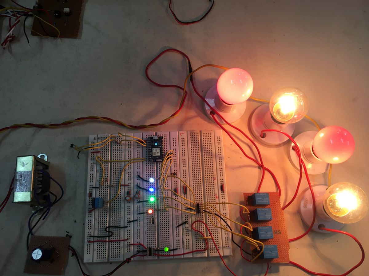
Fig. 1: Prototype of Arduino based Bluetooth AT Commands Test Project
The Arduino Pro Mini manages the exchange of data between the serial application on the desktop computer and the Bluetooth module. The circuit is assembled the following way –
Power Supply – The circuit is powered by a battery which directly supplies to the Arduino board and the Bluetooth module.
HC-05 Bluetooth Module – HC-05 Bluetooth module is serial port protocol module. It operates on ISM band 2.4GHz with V2.0+EDR (Enhanced data rate). It can work in both Master and slave modes. The Bluetooth module has six pins – Enable, VCC, Ground, Transmit Data (TxD), Receive Data (RxD) and State. The Enable and State pin are unused and so not connected in the circuit. The VCC and Ground pins are connected to the common VCC and Ground. The TxD and RxD pins of the module are connected to the pins 10 and 11 of the Arduino Pro Mini respectively. These connections are summarized in the table below –
Table listing circuit connections between HC-05 Bluetooth Module and Arduino Pro Mini
Fig. 2: Table listing circuit connections between HC-05 Bluetooth Module and Arduino Pro Mini
Apart from these connections, the 34th pin of the module is wired to the pin 9 of the Arduino Pro Mini.
Desktop Computer – The computer is connected to the Arduino board through USB cable and transfers serial data to the board through Virtual serial communication using a hyper terminal application.

How the project works – 

The project device receives the user entered AT commands from the hyper terminal application. The commands are serially read over virtual serial communication and passed to the Bluetooth module. The Bluetooth module responds to the AT commands and the responses are again serially read and transferred to the desktop application.
The HC-05 Bluetooth module supports the following AT commands –
S.No Command Response Parameter
1 AT OK
2 AT+RESET OK
3 AT+VERSION? +VERSION:<Param> OK Param : firmware version
4 AT+ORGL OK
5 AT+ADDR? +ADDR:<Param> OK Param: address of Bluetooth module
6 AT+NAME=<Param> OK Param: Bluetooth module name (Default :HC-05)
AT+NAME? +NAME:<Param> OK (/FAIL) Param: Bluetooth module name (Default :HC-05)
7 AT+RNAME?<Param1> 1. +NAME:<Param2> OK 2. FAIL Param1,Param 2 : the address of Bluetooth device
8 AT+ROLE=<Param> OK Param: 0- Slave 1-Master 2-Slave-Loop
AT+ ROLE? +ROLE:<Param> OK Param: 0- Slave 1-Master 2-Slave-Loop
9 AT+CLASS=<Param> OK Param: Device Class
AT+ CLASS? 1. +CLASS:<Param> OK 2. FAIL Param: Device Class
10 AT+IAC=<Param> 1.OK 2. FAIL Param: GIAC (Default : 9e8b33)
AT+IAC +IAC:<Param> OK Param: GIAC (Default : 9e8b33)
11 AT+INQM=<Param>,<Param2>, <Param3> 1.OK 2. FAIL Param: 0——inquiry_mode_standard 1——inquiry_mode_rssi Param2: Maximum number of Bluetooth devices to respond to Param3: Timeout (1-48 : 1.28s to 61.44s)
AT+ INQM? +INQM :<Param>,<Param2>, <Param3> OK Param: 0——inquiry_mode_standard 1——inquiry_mode_rssi Param2: Maximum number of Bluetooth devices to respond to Param3: Timeout (1-48 : 1.28s to 61.44s)
12 AT+PSWD=<Param> OK Param: PIN code (Default 1234)
AT+ PSWD? + PSWD :<Param> OK Param: PIN code (Default 1234)
13 AT+UART=<Param>,<Param2>,<Param3> OK Param1: Baud Param2: Stop bit Param3: Parity
AT+UART? +UART=<Param>,<Param2>, <Param3> OK Param1: Baud Param2: Stop bit Param3: Parity
14 AT+CMODE=<Param> OK Param: 0 – connect fixed address 1 – connect any

address 2 – slave-Loop


AT+ CMODE? + CMODE:<Param> OK Param: 0 – connect fixed address 1 – connect any address 2 – slave-Loop
15 AT+BIND=<Param> OK Param: Fixed address (Default 00:00:00:00:00:00)
AT+ BIND? + BIND:<Param> OK Param: Fixed address (Default 00:00:00:00:00:00)
16 AT+POLAR=<Param1,<Param2> OK Param1: 0- PIO8 low drive LED 1- PIO8 high drive

LED Param2: 0- PIO9 low drive LED 1- PIO9 high drive LED


AT+ POLAR? + POLAR=<Param1>,<Param2> OK Param1: 0- PIO8 low drive LED 1- PIO8 high drive LED Param2: 0- PIO9 low drive LED 1- PIO9 high drive LED
17 AT+PIO=<Param1>,<Param2> OK Param1: PIO number Param2: PIO level 0- low 1- high
18 AT+IPSCAN=<Param1>,<Param2>,<Param3>,<Param4> OK Param1: Query time interval

Param2 : Query duration Param3 : Paging interval Param4 : Call duration

AT+IPSCAN? +IPSCAN:<Param1>,<Param2>,<Param3>,<Param4> OK Param1: Query time interval Param2 : Query duration Param3 : Paging interval Param4 : Call duration
19 AT+SNIFF=<Param1>,<Param2>,<Param3>,<Param4> OK Param1: Max time Param2: Min time Param3: Retry time Param4: Time out
AT+ SNIFF? +SNIFF:<Param1>,<Param2>,<Param3>,<Param4> OK Param1: Max time Param2: Min time Param3: Retry time Param4: Time out
20 AT+SENM=<Param1>,<Param2> 1. OK 2. FAIL Param1:

0——sec_mode0+off

1——sec_mode1+ non_secure

2——sec_mode2_ service

3——sec_mode3_l ink

4——sec_mode_u nknown

Param2:

0——hci_enc_mod e_off

1——hci_enc_mod e_pt_to_pt

2——hci_enc_mod e_pt_to_pt_and_b cast


AT+ SENM? + SENM:<Param1>,<Param2> OK Param1:

0——sec_mode0+off

1——sec_mode1+ non_secure

2——sec_mode2_ service

3——sec_mode3_l ink

4——sec_mode_u nknown

Param2:

0——hci_enc_mod e_off

1——hci_enc_mod e_pt_to_pt

2——hci_enc_mod e_pt_to_pt_and_b cast


21 AT+PMSAD=<Param> OK Param: Authenticated Device Address
22 AT+ RMAAD OK
23 AT+FSAD=<Param> 1. OK 2. FAIL Param: Device address
24 AT+ADCN? +ADCN:<Param> OK Param: Device Count
25 AT+MRAD? + MRAD:<Param> OK Param: Recently Authenticated Device Address
26 AT+ STATE? + STATE:<Param> OK Param: “INITIALIZED” “READY” “PAIRABLE” “PAIRED” “INQUIRING” “CONNECTING” “CONNECTED””DISCONNECTED” “NUKNOW”
27 AT+INIT 1. OK 2. FAIL
28 AT+INQ +INQ: <Param1>, <Param2>, <Param3> …. OK Param1:Address Param2 : Device Class Param3 : RSSI Signal strength
29 AT+ INQC OK
30 AT+PAIR=<Param1>,<Param2> 1. OK 2. FAIL Param1 :Device Address Param2:Time out
31 AT+LINK=<Param> 1. OK 2. FAIL Param : Device Address
32 AT+DISC 1. +DISC:SUCCESS OK 2. +DISC:LINK_LOSS OK 3. +DISC:NO_SLC OK 4. +DISC:TIMEOUT OK 5. +DISC:ERROR OK Param : Device Address


33 AT+ENSNIFF=<Param> OK Param : Device Address
34 AT+ EXSNIFF =<Param> OK Param : Device Address


Fig. 3: Table listing AT commands of HC-05 Bluetooth Module and their response

During the testing of the Bluetooth module, the following commands were passed for which the response given in the table below were received.
Table listing color coding for terminals of servo motor
Fig. 4: Circuit Diagram of Arduino based Bluetooth AT Commands Test Project
These responses were observed on the Hyper Terminal Application. If the responses are not received on the desktop application, the circuit connections should be checked and baud rate must be verified. During testing, it was observed that baud rate needs to be set to 9600 bits per second initially but later it needs to be set to 38400 bits per second for running the AT commands. 
Check out the Arduino code to learn how the Arduino board manages serial data between the desktop and the Bluetooth module.

Programming Guide – 

For enabling virtual serial communication, SoftwareSerial.h needs to be imported. An object of Software serial type is instantiated and mapped to Arduino pins 10 and 11.
#include <SoftwareSerial.h>
SoftwareSerial mySerial(10, 11); // RX, TX
The setup() function is called in which the baud rate for communication with the PC is set to 9600 bits per second. The pin 9 which is connected to  the 34th pin of the Bluetooth Module is set to digital output and set to HIGH logic using pinMode() and digitalWrite() methods. Some initial messages are sent serially to the hyper terminal application and baud rate of the software serial port is set to 38400 bits per second for communication with the Bluetooth module.
void setup() {
Serial.begin(9600);
pinMode(9,OUTPUT); digitalWrite(9,HIGH);
Serial.println(“Engineers Garage:”);
Serial.println(“Enter AT commands:”);
mySerial.begin(38400);
}
The loop() function is called in which the response from the Bluetooth module is checked and if available is written to the serial port. Similarly, if any AT command from the desktop is available, it is read and written to the Bluetooth module.
Note: Get the complete code in the code section.
This completes the Arduino sketch for the Bluetooth Module Testing Project. Get a computer, assemble the circuit, launch a hyper terminal application and get hands dirty. It’s time to test.

You may also like:


  • What are the top 4G modems available in India?

  • What are the top development boards for AI and ML?

  • What are LoRa gateways and what types are available?

  • How does LoRa modulation enable long-range communication?

  • What is IP geofencing?

Project Source Code

###

//Program to
#include 
SoftwareSerial mySerial(10, 11); // RX, TX
void setup() {
Serial.begin(9600);
pinMode(9,OUTPUT); digitalWrite(9,HIGH);
Serial.println("Engineers Garage:");
Serial.println("Enter AT commands:");
mySerial.begin(38400);
}
void loop()
{
if (mySerial.available())
Serial.write(mySerial.read());
if (Serial.available())
mySerial.write(Serial.read());
}


###

Project Video


Filed Under: Tech Articles


Next Article

← Previous Article
Next Article →

Questions related to this article?
👉Ask and discuss on EDAboard.com and Electro-Tech-Online.com forums.


Tell Us What You Think!! Cancel reply

You must be logged in to post a comment.

EE TECH TOOLBOX

“ee
Tech Toolbox: 5G Technology
This Tech Toolbox covers the basics of 5G technology plus a story about how engineers designed and built a prototype DSL router mostly from old cellphone parts. Download this first 5G/wired/wireless communications Tech Toolbox to learn more!

EE Learning Center

EE Learning Center
“engineers
EXPAND YOUR KNOWLEDGE AND STAY CONNECTED
Get the latest info on technologies, tools and strategies for EE professionals.

HAVE A QUESTION?

Have a technical question about an article or other engineering questions? Check out our engineering forums EDABoard.com and Electro-Tech-Online.com where you can get those questions asked and answered by your peers!


RSS EDABOARD.com Discussions

  • Finding past posts on edaboard?
  • Industrial Relay Board Design for Motorcycle Use
  • I think i have devised a new type of "super_transformer" for the Electricity grid?
  • What is the purpose of this relay?
  • mosfet driver problem in regeneration mode

RSS Electro-Tech-Online.com Discussions

  • Pic18f25q10 osccon1 settings swordfish basic
  • Sump pit water alarm - Kicad 9
  • Anyone jumped from Easyeda std to Easyeda pro?
  • turbo jet fan - feedback appreciated.
  • More fun with ws2812 this time XC8 and CLC

Featured – LoRa/LoRaWan Series

  • What is the LoRaWAN network and how does it work?
  • Understanding LoRa architecture: nodes, gateways, and servers
  • Revolutionizing RF: LoRa applications and advantages
  • How to build a LoRa gateway using Raspberry Pi
  • How LoRa enables long-range communication
  • How communication works between two LoRa end-node devices

Recent Articles

  • How IoT network topologies work
  • The top five AI startups to watch in 2025
  • STMicroelectronics unveils SoC based on secure MCU
  • Nexperia’s 48 V ESD diodes support higher data rates with ultra-low capacitance design
  • Taoglas releases Patriot antenna with 18 integrated elements covering 600 to 6000 MHz

EE ENGINEERING TRAINING DAYS

engineering

Submit a Guest Post

submit a guest post
Engineers Garage
  • Analog IC TIps
  • Connector Tips
  • Battery Power Tips
  • DesignFast
  • EDABoard Forums
  • EE World Online
  • Electro-Tech-Online Forums
  • EV Engineering
  • Microcontroller Tips
  • Power Electronic Tips
  • Sensor Tips
  • Test and Measurement Tips
  • 5G Technology World
  • Subscribe to our newsletter
  • About Us
  • Contact Us
  • Advertise

Copyright © 2025 WTWH Media LLC. All Rights Reserved. The material on this site may not be reproduced, distributed, transmitted, cached or otherwise used, except with the prior written permission of WTWH Media
Privacy Policy

Search Engineers Garage

  • Electronic Projects & Tutorials
    • Electronic Projects
      • Arduino Projects
      • AVR
      • Raspberry pi
      • ESP8266
      • BeagleBone
      • 8051 Microcontroller
      • ARM
      • PIC Microcontroller
      • STM32
    • Tutorials
      • Audio Electronics
      • Battery Management
      • Brainwave
      • Electric Vehicles
      • EMI/EMC/RFI
      • Hardware Filters
      • IoT tutorials
      • Power Tutorials
      • Python
      • Sensors
      • USB
      • VHDL
    • Circuit Design
    • Project Videos
    • Components
  • Articles
    • Tech Articles
    • Insight
    • Invention Stories
    • How to
    • What Is
  • News
    • Electronic Product News
    • Business News
    • Company/Start-up News
    • DIY Reviews
    • Guest Post
  • Forums
    • EDABoard.com
    • Electro-Tech-Online
    • EG Forum Archive
  • DigiKey Store
    • Cables, Wires
    • Connectors, Interconnect
    • Discrete
    • Electromechanical
    • Embedded Computers
    • Enclosures, Hardware, Office
    • Integrated Circuits (ICs)
    • Isolators
    • LED/Optoelectronics
    • Passive
    • Power, Circuit Protection
    • Programmers
    • RF, Wireless
    • Semiconductors
    • Sensors, Transducers
    • Test Products
    • Tools
  • Learn
    • eBooks/Tech Tips
    • Design Guides
    • Learning Center
    • Tech Toolboxes
    • Webinars & Digital Events
  • Resources
    • Digital Issues
    • EE Training Days
    • LEAP Awards
    • Podcasts
    • Webinars / Digital Events
    • White Papers
    • Engineering Diversity & Inclusion
    • DesignFast
  • Guest Post Guidelines
  • Advertise
  • Subscribe