Acs712 current sensor can measure both direct and alternating current. For this post/tutorial/project I am going to measure only dc current. Formula which i derived and explained in the tutorial is only for direct current measurement. You can not use the below formula to measure alternating current with acs712 hall effect current sensor.
About Acs712
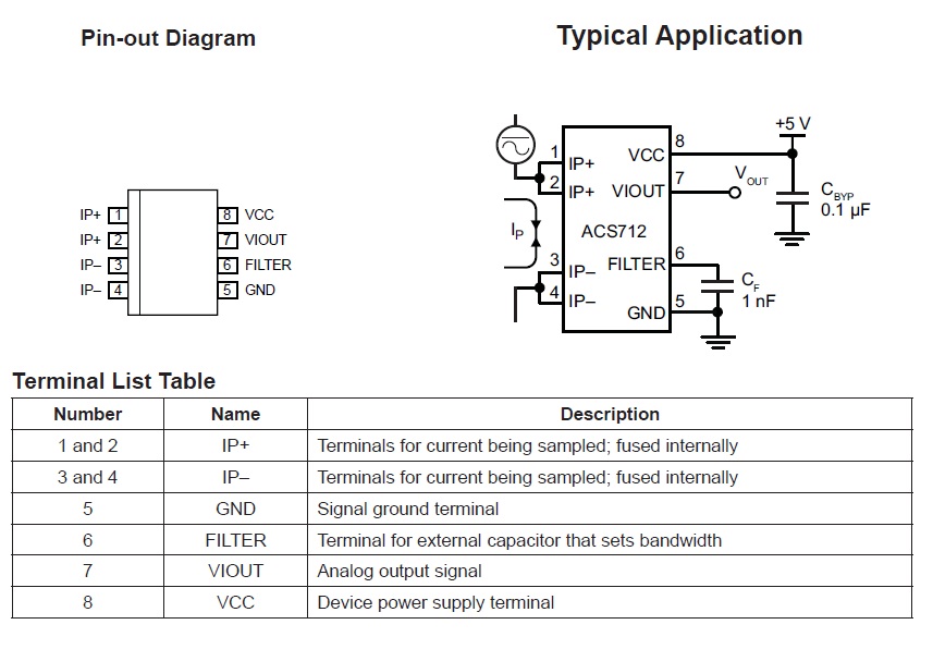
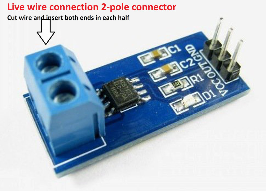
IP+ & IP-
Connect the sensor in series to the system whose current you want to measure. Cut the circuit wire and connect one end of wire to IP+ and other to IP-. Recall the high school lectures, current can be measured only in series. So don’t connect the sensor in parallel You may damage it by connecting it in parallel.
VIout
Viout is the voltage out pin. ACS712 outputs an analog signal in correspond to any variation across the IP+ and IP- pins or in other words it outputs analog voltage on VIOUT pin if their is any variation in the current.
Quiescent output voltage (VIOUT(Q)). The output of the device when the primary current is zero. For a uni-polar supply voltage,it nominally remains at VCC ⁄ 2. Thus, VCC = 5 V translates into VIOUT(Q) = 2.5 V. Variation in VIOUT(Q) can be attributed to the resolution of the Acs712. If the Acs712 is working on 5v(Vcc=5v) and their is no current flowing from input the Viout will be 2.5v. 2.5v is the base voltage at input of 5v, now any change in the input current will bring change in the output voltage. Viout decreases when current start flowing through the acs712 pins.
Acs712 is available in market in three ratings.
- ACS712ELCTR-05B-T
- ACS712ELCTR-20A-T
- ACS712ELCTR-30A-T
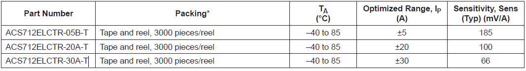
- ACS712ELCTR-05B-T can measure 5 to -5 Ampere current. Where 185mV change in Output voltage from initial state represents 1-Ampere change in Input current.
- ACS712ELCTR-20A-T can measure 20 to -20 Ampere current. Where 100mV change in Output voltage from initial state represents 1-Ampere change in Input current.
- ACS712ELCTR-30A-T can measure 30 to -30 Ampere current. Where 66mV change in Output voltage from initial state represents 1-Ampere change in Input current.
Acs712 Dc current measurement formula
Current = (AcsOffset – (Arduino measured analog reading)) / Sensitivity
- AcsOffset is normal voltage output at Viout pin when no current is flowing through the circuit.
- Arduino measured analog reading is the analog signal value read and converted to actual voltage from the analog channel to which acs712 output is connected.
- Sensitivity is Acs712 change in current representing 1 Ampere. For all the acs712 versions it is given in the above picture.
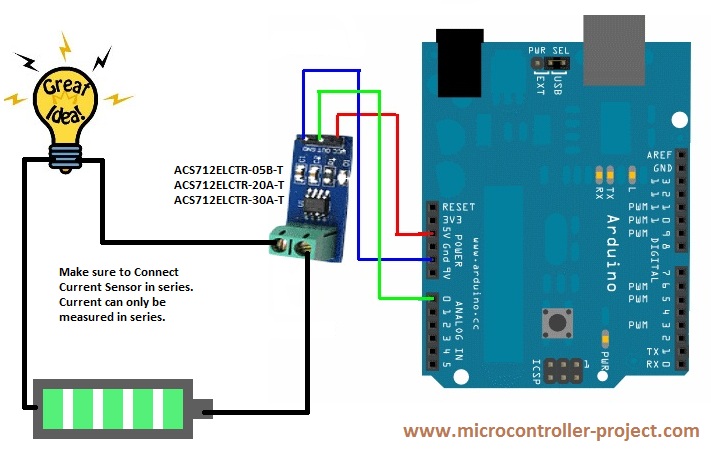
Arduino acs712 current sensor
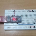
ACS712ELCTR-05B-T Interfacing with Arduino Uno
ACS712ELCTR-20A-T Interfacing with Arduino Uno
Project Code
Download the project code from the links given at the bottom of the Post.
ACS712ELCTR-30A-T Interfacing with Arduino Uno
Arduino direct current measurement – Project circuit diagram
You may also like:


Filed Under: Arduino, Arduino., Electronic Projects

Questions related to this article?
👉Ask and discuss on EDAboard.com and Electro-Tech-Online.com forums.
Tell Us What You Think!!
You must be logged in to post a comment.