In the previous tutorial, we discussed the digital input process for using Arduino. We also explained push buttons (momentary type buttons) and how to use them for data or command input via a digital input.
Any controller can interface and interact with other electronic devices in five ways: digital output, digital input, analog output, analog input, and serial communication.
In this tutorial, we will discuss analog output from Arduino and use it to fade an LED.
Analog signals
Electronics involves processing electronic signals. Electronic signals can occur in two forms: analog and digital.
Digital signals have discrete voltage levels and analog signals are continuous waves that change over time. You can think about analog signals as a continuous variation of voltage over time.
While digital signals are represented by rectangular waves, analog signals (if periodic) are typically represented by a sine wave. However, these may occur as continuous variations that may or may not follow a mathematical formula. Since they are continuous in nature, there’s no fixed range of values for these signals.
The periodic form of analog signals (sine wave) is used to carry information in analog communication systems — where the amplitude, frequency, or phase of the signal is modulated to carry electronic information. The non-periodic form of analog signals is used by sensors (and instrumentation devices) to communicate information about physical quantities (such as light intensity, temperature, humidity, pressure, etc.) to the computing devices (controllers or processors).
Analog sensors are designed to output a range of analog voltage that varies in relation to changes in a physical quantity. The analog (voltage) output from the sensor may follow a linear or non-linear curve in terms of the measured physical quantity.
The physical quantity is, then, measured by sampling the analog voltage against a range of values. In fact, even digital sensors first measure a physical quantity as a variation of the analog voltage and then convert it to a digitized signal by a built-in processor for digital output.
Similarly, actuators sense analog voltages from a control device (that can be a controller or processor) and move or position the target electro-mechanical system in relation to the analog voltage level. And even with digital actuators, the input digital signal is interpreted to an analog value to control the respective electro-mechanical system.
While periodic analog signals are useful in data communication, non-periodic analog signals are useful for setting up an interaction between electronics and the real world by the means of sensors and actuators. Any embedded controller must output analog voltages (Analog Output) to drive the actuators and sense the analog voltages (Analog Input), so as to interface with the (analog) sensors.
To output a true analog signal, a controller or processor must have a built-in, digital-to-analog converter (DAC) or be interfaced with an external DAC. Most of the Arduino boards do not have a built-in DAC and fail to provide true analog output.
However, the majority of the Arduino boards can output pulse-width modulated (PWM) signals that approximate or come close to the analog voltage levels. Based on all of the Arduino boards, only the MKR and Zero boards have one DAC (DAC0 at A0 pin) each, and the Due boards have two DAC (DAC0 and DAC1).
Pulse Width Modulation (PWM)
The non-periodic analog signals used by sensors and actuators are continuous but limited between a range of voltage levels. These signals are also sampled against a defined range of mathematical values. As the voltage level of these signals is confined, there’s an approximation of the analog signal rather than a true analog signal. But this works well for the purpose of computing or controlling.
The most common way of generating a signal that approximates the analog voltage levels in a defined range is PWM.
Similar to digital signals, PWM signals are rectangular. The difference is that PWM signals are periodic rectangular signals of fixed (or set) frequency, of which the duty cycle can be altered. By altering the duty cycle of a fixed-frequency periodic rectangular wave, the signal can approximate to analog voltage levels in a defined range. The maximum analog voltage that such a signal can approximate is the amplitude of the rectangular wave.
The other voltage levels that can be approximated by a PWM signal depends on the allowed variation of the duty cycle.
For example, let’s say the amplitude of the PWM signal is 5V. If the duty cycle is controlled by an 8-bit register, 256 (2^8) voltage levels can be achieved between 0 to 5V. If we assume that these voltage levels are precisely spaced by an equal interval, each voltage level will differ by 19.6 mV (5V/255) from the adjacent voltage levels.
If the duty cycle is controlled by a 10-bit register of the same amplitude, 1024 (2^10) voltage levels can be achieved between 0 and 5V. In this case, each voltage level will differ by 4.9 mV from the adjacent voltage levels.
The frequency of the PWM signal does not have any impact on the number of voltage levels that can be achieved by the signal. The higher the frequency of the PWM signal, the better the precision of the voltage level. The frequency of the PWM signal also plays an important role when the signal is used for high-speed switching operations in a circuit or when the PWM signal is used for audio applications.
In relation to actuators (or similar output devices), the only concern is the allowed variation of the duty cycle. The greater the resolution of the duty cycle, the more precise the PWM signal will approximate to the analog voltage curve. A PWM signal must approximate to a non-periodic analog voltage in a linear and predictable manner.
Arduino boards & PWM
PWM signals can be generated by calling the analogWrite() function when using Arduino boards.
The PWM outputs are available at the following pins, depending on the board.
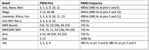
In addition to PWM capabilities at the above-mentioned pins, MKR and Zero boards have one true analog output (DAC0) at pin A0, and Due boards have two true analog outputs (DAC0 and DAC1). Apart from these PWM sources, PWM signals with different frequencies can also be generated when using Arduino by bit-banging and by using the timers/counters from the onboard AVR controller.
The analogWrite() function has been written to generate the PWM signals for the above-specified frequencies at specified pins. However, the details are abstract for how it uses timers/counters of the on-board controller to generate the PWM signals for fixed frequencies.
Here is the source code for the analogWrite() function from wiring_analog.c file.
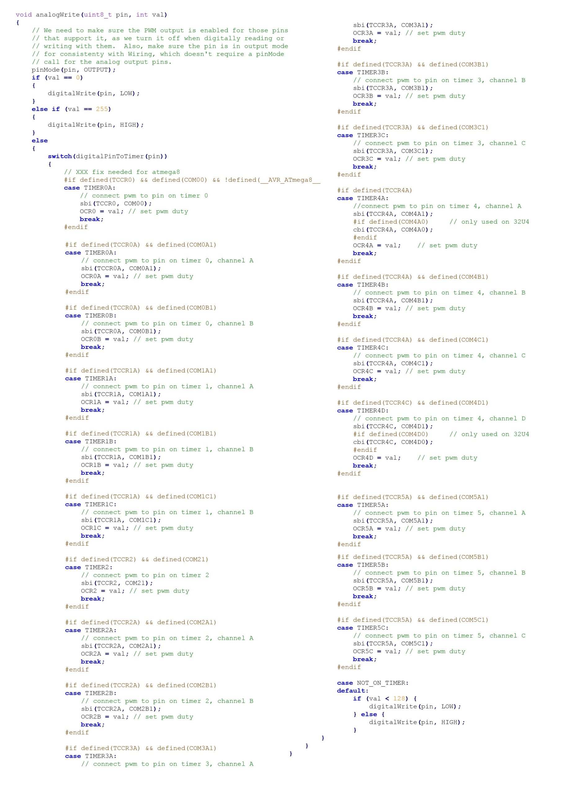
The analogWrite() function uses a combination of the timer/counter programming and bit-banging (in the case of 0% and 100% duty cycles, and for the non-timer default case) to generate PWM signals.
The pinMode() function is also called inside the body of the analogWrite() function. So, there’s no need to use the pinMode() function to set the pin as the output before calling the analogWrite() function. The PWM signals on pins 5 and 6 may have a higher duty cycle than expected. This is because these pins use the same internal timer, which is employed by the delay() and Milliis() functions.
The analogWrite() function
The analogWrite() function has the following syntax:
analogWrite(pin, value)
It requires two arguments:
1. The pin number where the PWM signal should be generated
2. The resolution value of the duty cycle.
The pin number must be a valid pin so the PWM can be generated. The PWM pins are marked by the tilde sign (~) on the Arduino board. The resolution value can be any positive integer between 0 and 255. A value of 0 signifies a 0% duty cycle and a value of 255 signifies a 100% duty cycle.
Other duty cycles can be obtained by using intermediate values, such as 64 for a 25% duty cycle, 127 for a 50% duty cycle, 191 for a 75% duty cycle, and so on.
Arduino UNO & PWM
Arduino UNO has six PWM pins: 3, 5, 6, 9, 10, and 11. These pins are connected to the on-board AVR ATmega328P microcontroller via:
- PB3 (Port B, Bit 3)
- PB2 (Port B, Bit 2)
- PB1 (Port B, Bit 1)
- PD6 (Port D Bit 6)
- PD5 (Port D Bit 5)
- PD3 (Port D Bit 3)
For the PWM generation at PB3, PB2, PB1, PD6, PD5, and PD3, these are the timer/counter and associated registers used:

For the PWM generation, the timer/counter and control registers are configured first. A value in the output compare register is stored, which essentially decides the duty cycle for the PWM signal. This value is, then, matched with the timer/counter register to set or clear the output bit.
In this tutorial, we are not using bit-banging or the timer/counter to generate the PWM signals, but will generate the PWM output using the analogWrite() function.
LED fading recipe using analogWrite()
In this recipe, we will fade an LED by using the PWM signal from Arduino. The PWM signal will be generated using the analogWrite() function.
Components required
1. Arduino UNO x1
2. LED x1
3. 330 Ohms Resistor x1
4. Breadboard x1
5. Male-to-Male Jumper Wires or Connecting Wires
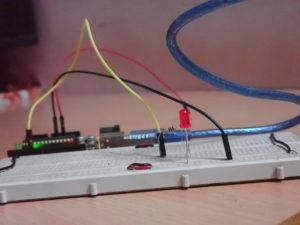
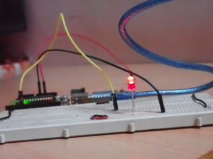
Circuit connections
Connect the digital I/O pin 5 from Arduino UNO with the anode of the LED. Then, connect the cathode of the LED with a series resistor of 330 Ohms and ground the other terminal from the resistor. The DC supply voltage and ground can be given to the circuit from the 5V power pin and one of the ground pins of the Arduino UNO.
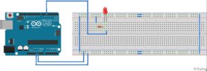
Circuit diagram

Arduino sketch
int i = 0;
void setup() {
pinMode(5, OUTPUT);
}
void loop() {
for(i=0; i<255; i++)
{
analogWrite(5, i);
delay(20);
}
for(i=255; i>0; i–)
{
analogWrite(5, i);
delay(20);
}
}
How the project works
The LEDs are current-controlled display devices. They are similar to signal diodes. This means the current flows through the LED when it is forward biased by an application of the appropriate voltage.
In a forward-biased condition, the LED starts glowing. When the forward voltage is removed from the LED, the current stops flowing through it and the light stops glowing. The intensity of the light emitted by an LED depends on the current drawn by it. An LED typically requires 12 mA to 30 mA current for maximum illumination. Most LEDs draw 5 mA for normal illumination.
The voltage-current characteristics of an LED are similar to signal diodes. In a forward-biased condition, the current through an LED increases based on the applied forward voltage.
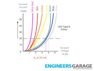
By increasing or decreasing the applied forward voltage, the current moving through the LED can be increased or decreased, respectively — and the intensity of light emitted from it can also be increased or decreased.
Arduino UNO has 6 PWM channels at pins 3, 5, 6, 9, 10, and 11 of the board. These channels can be used to output the PWM signal, which is an approximation of the analog voltage. The PWM signal can be generated on one of these pins using the analogWrite() function, bit-banging, or using the timer/counter.
When using the analogWrite() function, the PWM signal of fixed frequency is generated on Arduino’s PWM pins. For Arduino UNO, the PWM signal of 980 Hz is generated at pins 5 and 6, and the PWM signal of the 490-Hz frequency is generated at the remaining PWM pins when calling the analogWrite() function.
The analog output from the PWM pin can be altered by changing the duty cycle of the PWM signal. The amplitude of the PWM signal generated on Arduino is 5V.
- When the duty cycle is set to 100%, the PWM signal approximates to 5V
- When the duty cycle is set to 50%, the PWM signal approximates to 2.5V
- When the duty cycle is set to 0%, the PWM signal approximates to 0V and so on.
When the light intensity of the LED is increased and faded alternatively in a continuous fashion, this effect is called LED fading. It’s achieved by applying a continuously increasing and decreasing forward voltage to the LED in an alternate manner. It’s also possible to generate an alternating voltage by continuously altering the duty cycle of a PWM signal. Such a PWM signal has the same effect on an LED as if a rectified sine wave signal has been applied to the LED.

When creating an approximation of the rectified sine wave, the PWM signal of a fixed frequency is applied to the LED. Also, the duty cycle of the PWM signal is first increased by the integer steps, from 0 to a maximum value (255), and then reduced by the integer steps, from a maximum value (255) and then back to 0. For each increase or decrease in the duty cycle, the PWM wave must remain active for that same time period.
For example, let’s say the PWM wave has a frequency of 1000 Hz. So, 1000 PWM pulses of a certain duty cycle are generated from the channel in one second. If the PWM pulse train remains active for 20 milliseconds for a given duty cycle, 20 PWM pulses (20 milliseconds*1000Hz/1000) are applied to the LED for each duty cycle.
If the duty cycle is increased and then decreased at an interval every 20 milliseconds, the generated PWM signal approximates to a rectified sine wave with a time period of 10.2 seconds (20 milliseconds x 255 x 2). This is provided the duty cycle is continuously increased and decreased by an 8-bit (2^8) resolution.
So, when applying such PWM signals, the LED must glow to full illumination in 5.1 seconds and then fade to no illumination in the next 5.1 seconds. This will create an effect of the LED fading at an interval of 10.2 seconds.
When creating such an effect, the LED can be interfaced with the Arduino channel in both ways — where the channel may serve as the current source or current sink. In either case, the forward voltage requires altering. If the LED is interfaced with the channel (such that the channel acts as a current source), the LED will gradually illuminate when the duty cycle of the applied PWM signal is increased by the integer steps. The LED will, then, fade when the duty cycle of the applied PWM signal is decreased by integer steps.
The opposite happens when the LED is interfaced with the channel such that the channel acts as a current sink. However, interfacing the LED in a way that the channel act as the current sink has a drawback. In such cases, the LED will start illuminating only when the PWM signal approximates to a voltage that’s greater than the forward voltage of the LED.
This means that the LED’s fading effect can be best viewed when the LED is interfaced with the channel, such that the PWM channel act as the current source for the LED. In this case, the LED will always remain in the forward-biased region of the VI curve.

Programming guide
To create the effect of LED fading, it’s necessary to generate the PWM signal that approximates to a rectified sine wave.
A counter variable using the i of int type is defined as a global variable. In the setup() function, pin 5 is typically set as the output. But this is unnecessary because the channel is to be employed as the PWM source, using the analogWrite() function. Pin 5 from the Arduino UNO generates a PWM signal of 980 Hz frequency.
In the loop() function, a for loop is run in which the variable i is used as the counter, such that the value of i is initialized to 0 and increased by one in each step — until it is less than 256. The analogWrite() function is used to generate the PWM signal at pin 5 with the duty cycle set to i.
The delay() function is used in each loop with 20 milliseconds as the argument so that the PWM pulse train remains active for each of the duty cycles for an interval of 20 milliseconds. As pin 5 generates a PWM signal of 980 Hz frequency, approximately 19 to 20 PWM pulses of each duty cycle are applied to the LED. While the duty cycle increases at 20 milliseconds interval, the LED gradually glows to its full illumination in 5.1 seconds and in 255 steps.
Immediately, after exiting the first for loop, another loop is run in which the counter value is initialized to 255 and decreased by one in each step — until it is greater than 0. The PWM signal is generated on pin 5, like in the previous for loop, but with decreasing the duty cycle in each step at an interval of 20 milliseconds. As a result, the LED gradually fades to no illumination in 5.1 seconds and in 255 steps.
The loop() function iterates for an infinite number of times. So, the LED keeps on illuminating and fading alternatively as if a rectified sine wave has been applied to it.
In the next tutorial, we will discuss analog input when using Arduino.
Demonstration video:
Arduino sketch:
You may also like:


Filed Under: Arduino., Featured Contributions, Tutorials

Questions related to this article?
👉Ask and discuss on EDAboard.com and Electro-Tech-Online.com forums.
Tell Us What You Think!!
You must be logged in to post a comment.