In the previous tutorial, we discussed digital output from Arduino to drive an LED. A controller can interface and interact with other devices in five ways: digital output, digital input, analog output, analog input, and serial communication.
In this tutorial, we will use digital input from Arduino to read the state of a tactile switch — using it to switch ON/OFF an LED.
Switches
Switches are electrical devices designed to interrupt the flow of electricity in a circuit. A switch can make or break an electrical connection. In a circuit, it’s connected between two points at different potentials. At one point there’s a load that is ready to consume the power (current) and at the other point is a source that’s ready to supply the power (current).
A switch can be either fully ON or fully OFF. In a fully ON condition, it creates a closed path between the source and load, so that the load can consume power (current) from the source. In a fully OFF condition, it open-circuits the path between the load and the source, so that no power is consumed by the load.
The switches are primarily used to switch the ON/OFF power supply to the circuit or to part of the circuit. Essentially, any electrical or electronic device has a switch to turn ON/OFF the device. Such switches may be mechanical or electronic. The switches used for switching purposes are a locked type and they remain in a fully ON or OFF state once toggled.
Additionally, switches can be used as input devices and to supply digital logic for a controller or processor channel. Such switches are considered a momentary type. They remain in a fully ON state unless they are pressed or activated, and then they switch back to fully OFF state as they are released or deactivated.
Types of switches
As mentioned, switches can be mechanical or electronic. Mechanical switches are activated by pressing, moving, or touching their contacts. The number of power circuits (loads) that can be switched by a switch are called “pole.” The number of states that loads can switch to using a switch is called “throw.”
Mechanical switches are classified in several ways, including:
- The number of contacts (single-contact or multi-contact)
- The number of poles and throws (SPST, SPDT, DPST, DPDT)
- The method of actuation, construction, and state (locked or momentary).
Mechanical switches include:
1. Single Pole Single Throw (SPST)
2. Single Pole Double Throw (SPDT)
3. Double Pole Single Throw (DPDT)
4. Double Pole Double Throw (DPDT)
5. Push Button
6. Toggle Switch
7. Float Switch
8. Limit Switch
9. Rotary Switch
10. Pressure Switch
11. Flow Switch
12. Joystick Switch
13. Temperature Switch
Electronic switches are active components that can operate as a switch by controlling the flow of current between their terminals. These components generally operate as a one-way switch.
However, it’s possible to design two-way switches as well by using more than one switching component in the appropriate circuit.
These active components can operate as a switch:
1. Power Diodes/Signal Diodes
2. Bipolar Transistors
3. MOSFET
4. IGBT
5. SCR
6. TRIAC
7. DIAC
8. Gate Turn-Off Thyristor
Data input
For digital/logical input, momentary type switches are used such as the push buttons. The controller or processor evaluates the state of the switch (when it is pressed and released), using it when appropriate.
The event of pressing (or releasing) the switch can be interpreted as “data input,” according to the program.
Pull-up and pull-down
When a channel of Arduino is configured as “input,” it remains in a high-impedance state. This means it has an extremely low demand from the external source, making the state of the switch unpredictable if it’s left unconnected (called “floating”).
If the switch is directly interfaced to a current source or to the ground, it will remain in a floating state until the switch is pressed. So, the pin must be hard-wired to the opposite logic by default. This hard-wiring must be done via a resistor to protect the channels (pins) of the controller.
If a pin is hard-wired to ground, so that it can read a HIGH logic (in a positive logic system) via the switch, the resistor used is called a pull-down resistor. If a pin is hard-wired to the DC voltage, so that it can read a LOW logic (in a positive logic system) via the switch, the resistor used is called a pull-up resistor.
When a pin is configured as INPUT_PULLUP, it’s connected to the internal pull-up resistor, meaning it must connect to the ground through the switch to read logical LOW as input.
When a pin is configured as INPUT or INPUT_PULLUP, if the applied voltage is negative or greater than supply rail voltage (5 or 3V), the pin can get damaged or destroyed.
The pins can source or sink up to 40 mA if they are interfaced by a switch with external pull-up and pull-down resistor respectively. So, in either case, it must be ensured that the current through the channel (pin) should not exceed 30 or 40 mA.
When a pin is configured as INPUT or INPUT_PULLUP, a voltage greater than 3V and a voltage greater than 2V is read as logical HIGH in 5V and 3.3V boards respectively. A voltage less than 1.5V and a voltage less than 1V is read as logical LOW in 5V and 3.3V boards, respectively.
Reading digital input
The AVR ports have true, read-modify-write functionality. Each pin consists of three registers (internal registers of AVR controller) bits: DDxn, PORTxn, and PINxn. The DDxn bit controls the direction of the pin.
When the pin is configured as an output, this bit is set to logical ONE, and when the pin is configured as input, this bit is set to logical ZERO. When a pin is used as an output, if logical ONE is written on the PORTxn bit, the pin is set to HIGH and if logical ZERO is written on the PORTxn bit, the pin is set to LOW.
When a pin is used as input — and if logical one is written on the PORTxn bit — the internal pull-up is activated and if logical ZERO is written on the PORTxn bit, the internal pull-up resistor is switched off.
When a pin is configured as input, the input logic is read in the PINxn bit. The PINxn register bit has a preceding latch that acts as a synchronizer. This latch is closed when the system clock goes LOW and is transparent when the system clock is HIGH.
The signal value is latched in the PINxn register bit when the system clock goes LOW. Even if the input signal arrives at the falling edge of the system clock, it’ read in the PINxn register bit in the immediate next falling edge of the system clock.
This diagram is a timing diagram for reading an externally applied pin value:

It takes the single-system clock pulse to read a digital input by Arduino’s AVR controller. Considering that the Arduino is clocked by a 16 MHz crystal, it takes 62.5 nanoseconds to read the input. As a result, the state of a switch is always evaluated if conditional to avoid unwanted redundancy in the data input.
Programming Arduino for digital input
For reading digital input from Arduino, the pin must be configured as INPUT or INPUT_PULLUP using the pinMode() function. For example, this statement configures pin 3 as the INPUT:
pinMode(3, INPUT);
If a pin is configured as INPUT, it must use an external pull-up or pull-down resistor. A pin can also be configured as INPUT_PULLUP when it uses an internal pull-up resistor. This statement configures pin 3 as the INPUT_PULLUP:
pinMode(3, INPUT_PULLUP);
If the pin is configured as INPUT_PULLUP, it must be interfaced via the switch to the ground so that it reads logical LOW from the externally applied signal.
The pin value can be read using the digitalWrite() function. The read value must be compared with LOW/0/False or HIGH/1/True in if conditional to execute the desired follow-up action. For example:
if (digitalRead(3) == LOW)
{
digitalWrite(2,LOW);
}
Push-button controlled LED recipe
In this recipe, we will switch ON and OFF an LED with a switch. The LED will remain ON by default. When a push button is pressed, the LED will switch OFF momentarily.
Components required:
1. Arduino UNO x1
2. LED x1
3. Tactile Switch x1
4. 330 Ohms Resistor x1
5. Breadboard x1
6. Male-to-Male Jumper Wires
Circuit connections
First, connect the digital I/O pin 2 of Arduino UNO with the anode of the LED. Then, connect the cathode of the LED with a series resistor of 330 Ohms and ground the other terminal of the resistor.
Next, connect a push button at pin 3 of Arduino UNO and ground the other terminal of the button. The DC supply voltage and ground can be given to the circuit from the 5V power pin, and one of the ground pins of the Arduino UNO, respectively.

Circuit diagram

Programming guide
To control the LED, pin 2 (where the LED is interfaced) must be configured as the digital output. The pin 3 (where the tactile switch is interfaced) must be configured as the digital INPUT_PULLUP.
These pin configurations are set in setup() function as follows:
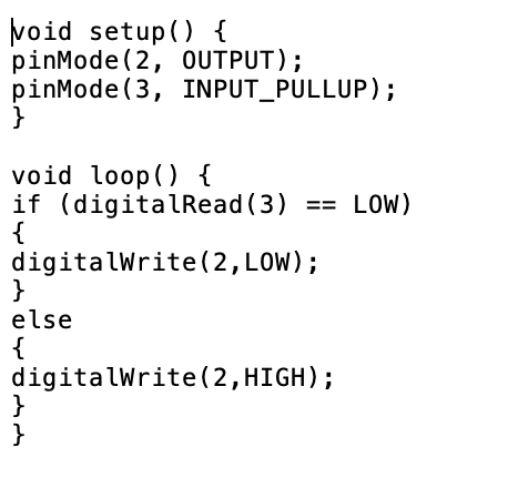
void setup() {
pinMode(2, OUTPUT);
pinMode(3, INPUT_PULLUP);
}
The LED must switch ON whenever the button is pressed. As the button is configured as INPUT_PULLUP, no external pull-up or pull-down resistor is used and the switch can only read as logical LOW.
The state of the switch is read using the digitalRead() function and compared with the logical LOW. If it is LOW, this means that the LED is switched OFF — which is done by setting the output of pin 2 to LOW using digitalWrite() function.
However, as the LED should remain ON by default, the output of pin 2 is set to HIGH in the else clause. This code is written within loop() function as follows:
void loop() {
if (digitalRead(3) == LOW)
{
digitalWrite(2,LOW);
}
else
{
digitalWrite(2,HIGH);
}
}
The project
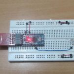
The switch is connected with Arduino through the internal pull-up at pin 3, so the pin can read as logical LOW from the external circuit. The LED is connected at pin 2 from Arduino in the circuit, so that it’s switched ON when the current is sourced to it by setting the interfaced pin to HIGH.
The Arduino is also programmed so that whenever the switch is pressed and a logical LOW is read at pin 3, the LED is switched OFF by setting the pin 2 to LOW. The pin 2 is set to the logical HIGH in else clause, so that the LED remains switched ON by default.


OLYMPUS DIGITAL CAMERA
Do-It-yourself
Rewrite the code of this recipe to toggle the state of the LED for pressing the push button. When the button is pressed once, the LED must switch OFF permanently. When the button is pressed again, the LED must switch ON again.
In the next tutorial, we will discuss the steps for generating analog output (PWM signal) from Arduino.
Demonstration video:
Arduino sketch:
You may also like:
Filed Under: Arduino., Tutorials


Questions related to this article?
👉Ask and discuss on Electro-Tech-Online.com and EDAboard.com forums.
Tell Us What You Think!!
You must be logged in to post a comment.