 Timing plays an important part in our life. It’s normal for a human to allocate time for future plans. We only need brain and a clock to decide what is the current time and how much time has passed. Similarly, a microcontroller can also calculate time. It serves the purpose of brain as in case of human and the clock is provided by oscillator. For us, wastage of a second may not be important but for microcontroller a microsecond is very crucial.
Timers with NRF24LE1
Timing plays an important part in our life. It’s normal for a human to allocate time for future plans. We only need brain and a clock to decide what is the current time and how much time has passed. Similarly, a microcontroller can also calculate time. It serves the purpose of brain as in case of human and the clock is provided by oscillator. For us, wastage of a second may not be important but for microcontroller a microsecond is very crucial.
In this article you will find answer to questions like – How we can use NRF to keep a track of elapsed time, how we can generate delay of specified period and much more.
Most microcontrollers have inbuilt functionality know as Timers. These Timers are used to keep a track of time. Also they can be used as counter to count pulses. The NRF24LE1 has three timers Timer0, Timer1 and Timer2. We will be discussing only Timer0 in the present article.

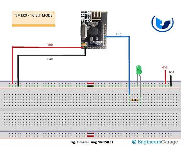
Fig. 1: Prototype of NRF24LE Module based Timer
The timer uses clock frequency to update time. It uses registers to hold the value of time. For example, if we use a clock of 16 MHz which has a time period of 62.5 nS (nano seconds) then the timer register increments its value by 1 after every 62.5 mS. It also means that the smallest measurement we can take is 62.5 mS.
Fig. 2: Image of NRF24LE Module based Timer
We already discussed that the timer uses registers to store the value of time. In NRF24LE1 we can choose between 8-bit register, 13-bit register and 16-bit register. The selection of register affects the amount of time a timer can store. For example, an 8-bit register can store value up to 255. If we use 16 MHz frequency of time period 62.5 mS then the maximum amount of time that this register can store is (62.5 * 255) = 15.9 uS (micro seconds).
Now what if we change the frequency? Let’s try it out.
Let’s say my new frequency is 16MHz/8 = 2 MHz which means now the time period is 0.5 uS. Now if we use 8-bit register to hold the value of time then the maximum amount of time that this register can store is (0.5 * 255) = 127.5 uS (micro seconds). What we observe is, if we decrease the frequency, the maximum amount of time that register can store increases. The divider that we use to decrease the frequency is known as prescaler. We can change this prescaler to change the frequency. In NRF module the prescaler is inbuilt and fixed at 12. That means now frequency becomes 16/12 = 1.33 MHz.
We have to select the Timer0 to function as a timer or counter. For this we have TMOD (Timer Mode) register. The second bit of this register is used to select between timer and counter. If this bit is 0 then timer is selected and if 1 then counter is selected. We have to write this bit according to our requirement.
For Timer0, we have three modes:
1. Mode0 – this mode is used to select 13-bit register
2. Mode1 – This mode is for 16-bit register.
3. Mode2 – it is for 8-bit auto reload.
4. Mode3 – this mode is used to select one 8-bit register as timer/counter and other 8-bit as timer.
The first bit and zero bit of TMOD register is used to select between different modes. The various combinations of these bits refer to different modes. They are:
00 – Mode0
01 – Mode1
10 – Mode2
11 – Mode3
The registers which hold the value of time for timer0 are TL0 and TH0. These two registers are of 8-bit each. They can be combined to be used as 16-bit register or 13-bit register. TH0 holds the higher byte and TL0 holds the lower byte of data. Also if these registers get full, it is known as overflow. We can check if an overflow has occurred by checking the overflow flag in TCON (Timer Control) register. The bit number five represents the overflow flag. If flag is 1 then overflow has occurred. We can write a service routine which gets called when overflow occurs.
Overflow flags are automatically cleared when the service routine is called.
To start the timer we have to set the bit number four of TCON. If this bit is cleared that is 0, the timer will stop. We can also access this bit through TR (Timer Run) variable. If TR = 1, timer starts. If TR = 0, timer stops.
There are more features of timer like overflow, hardware control, gate control and pulse counter. We will be discussing these features in our upcoming articles.
We have written a code to understand the timers. We are using timer0 in mode1. We have created a delay of ……
Project Source Code
###
//Program to#include "reg24le1.h" // I/O header file for NRF24LE1#include// standard library #include// library containing string functions #include// standard I/O library sfr16 DPTR = 0X82; // declare functional register DPTR// main functionvoid main(){int i = 0;P1DIR = 0; // Port1 as outputP10 = 0; // Pin 0 of Port 1 lowEA = 1; // Enable global interruptTMOD = 0X01 ; // timer0 in 16bit mode1TR0 = 1; // start timer// infinite loopwhile(1){TH0 = 0; // initialise timer register upper byteTL0 = 0; // initialise timer register lower bytewhile(TF0 == 0); // wait for timer overflow flagTF0 = 0; // clear flagP10 =1; // make Pin0 of Port1 highTH0 = 0; // initialise timer register upper byteTL0 = 0; // initialise timer register lower bytewhile(TF0 == 0); // wait for timer overflow flagTF0 = 0; // clear flagP10 = 0; // make Pin0 of Port1 low}}###
Circuit Diagrams
Project Video
Filed Under: Tutorials
Filed Under: Tutorials

Questions related to this article?
👉Ask and discuss on EDAboard.com and Electro-Tech-Online.com forums.
Tell Us What You Think!!
You must be logged in to post a comment.