TRANSFORMERS – TYPES
Transformers primarily can be divided into two types: voltage transformers and current transformers.
Constant-voltage transformer changes the voltage of a system and is designed to operate with its primary connected to a constant-voltage supply and to provide a secondary voltage which largely remains constant from no load to full load. The currents of both primary and secondary vary with the load supplied by the transformer.
Variable-voltage transformer also changes the voltage of a system but is so designed that when operated with its primary connected to a constant-voltage supply, the secondary voltage varies widely with the load.
Current transformer is designed for changing the current of a system. The primary winding is connected in series with the circuit of which it is required to change the current. The voltage of both primary and secondary will change with the current of the system.
Constant-current transformers are so designed that a constant value of secondary current is supplied to the load regardless of the load on the transformer. The primary is connected to a constant-voltage source but the secondary voltage varies proportionally with the load.
Some common type of transformers is: Power transformers, Audio transformers, RF transformers, Auto transformers, Poly-phase transformers.
1. Power Transformer
Power transformers are primarily used to step down or step up voltages (and currents). The size of the transformer varies depending upon the application; small sized transformers are used in power section of various equipments whereas very larger transformers are used for supply of high voltage grid electricity. Power transformers are often used to provide a system with a large number of AC supplies of different voltages and currents.
Typically, voltage transformers for the transformation of a large amount of power, more than 500 kVA, are called power transformers. Transformers for general power transformation, whose rating is 500 kVA or less, are called distribution transformers. All the methods of cooling are employed for power transformers.
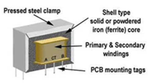
Construction of a typical laminated core (Core of E and I shaped laminations) power transformer is shown in figure.

Another popular design of power transformer using toroidal core is shown in the following figure. It given excellent linkages as primary and secondary are wound on the same core, though this design proves more expensive

Issues like wide frequency response, harmonic distortion, etc. are not relevant for power transformers.
2. Audio Transformer
Though very similar with power transformers with respect to their construction, they are usually quite smaller in size compared to power transformers. Audio transformers are designed for audio range of frequencies, i.e., for frequencies ranging from 20 Hz to 20 KHz and are used primarily in audio circuits.

In addition to other transformer characteristics, important characteristics of an audio transformer are the frequency response, total harmonic distortion and insertion loss.
3. RF Transformers
RF transformers are widely used in low-power electronic circuits for impedance matching to achieve maximum power transfer, for voltage step-up or step-down, and for isolating dc from two circuits while maintaining ac continuity. They are also used for common mode rejection and as baluns.
RF transformers are designed to function in the radio range of frequencies. Typically, it uses an air core but more effective flux linkage is obtained with the use of a core of iron or ferromagnetic material with higher permeability than air. Functions and design principles are similar to that of audio transformer.
4. Auto Transformers
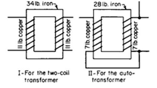
When the transformation ratio is not too large, an effective way of operating a transformer is an autotransformer. Normally used in power circuits, autotransformers use single winding and certain portions of the winding is used simultaneously as the primary and the secondary circuits. The autotransformer has only one coil, a certain portion of which is used for both the HV and LV windings. The number of turns of this coil is the same as would be required if it were used exclusively for the HV windings. Not only is the copper, core material requirement lesser in autotransformers. A comparison of a two winding transformer with an autotransformer is given in the following figure

Depending upon whether the transformer is used as a step-up or step down transformer, a part or full winding is used as a primary; and a part or full of the same winding as the secondary.
5. Poly-phase Transformers
The term ‘poly’ is used in transformers used for AC supplies with more than one phase, for e.g., three phase transformers. A polyphase transformer generally consists of several one phase transformers with separate electric circuits but having certain magnetic circuits in common. A three-phase transformer is shown in the figure
Filed Under: Articles


Questions related to this article?
👉Ask and discuss on Electro-Tech-Online.com and EDAboard.com forums.
Tell Us What You Think!!
You must be logged in to post a comment.