434 MHz RF Modules are commonly used in the electronics projects. These modules can transmit data at a rate of 1Kbps to 10Kbps and send or receive data over a distance of 50-60 metres. The module already has an impressive operational range which is suitable for most of the DIY projects. However, some projects may require transmitting data over a greater range.
The range of an RF module can be increased by attaching antennas of suitable size to the transmitter and receiver sections of the module or by increasing the transmission power of the module. Either of the two or both methods can be implemented to extend the operational range of an RF module.
In this project, the effect of increasing the transmission power over the operational range of the standard RF module has been inspected. The basic setups of RF transmitter and receiver were built on breadboards and the range was tested by altering the data transmission in outdoors. The range is predicted by measuring the exact distance between the receiver and transmitter sections using a measuring tape.
Components Required
| Sr. No. | Components Required | Quantity Required |
|---|---|---|
| 1 | RF Tx module(434Mhz) | 1 |
| 2 | RF Rx Module(434Mhz) | 1 |
| 3 | HT12E | 1 |
| 4 | HT12D | 1 |
| 5 | LED | 5 |
| 6 | Resistor – 1KΩ (Quarter watt) | 8 |
| 7 | Resistor – 1MΩ (Quarter watt) | 1 |
| 8 | Resistor – 50KΩ (Quarter watt) | 1 |
| 9 | Pushbutton | 4 |
| 10 | Battery – 9V | 2 |
| 11 | Breadboard | 2 |
| 12 | Connecting wires | – |
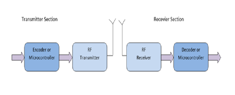
BLOCK DIAGRAM
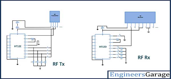
Circuit Connections
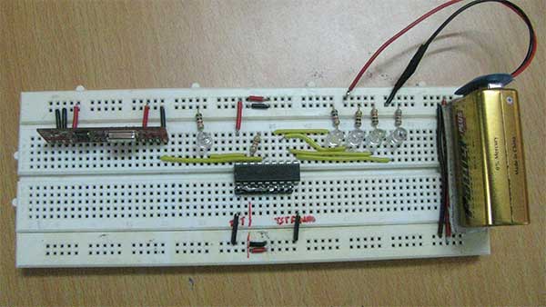
The circuit connections of the RF Module are done as specified by the datasheets of HT12E IC, HT12D IC, RF transmitter and RF receiver. These circuit connections are already explained in Basic Model of RF transmitter and receiver experiment. To test the effect of increasing transmission power on an operational range of the RF module, first, the operational range with modules powered by single 9V battery is observed. The circuit connections are made and the circuits are supplied power through the 9V battery or 9V portable power supply units. The circuits are taken to an open place where the distance between the receiver and the transmitter can be measured on a straight line using a measuring tape. The address bits of both encoder and decoder ICs are hard-wired to ground to configure the address bytes of the transmitter as well as the receiver to 0x00.
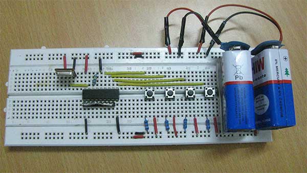
The data bits at the encoder IC are also hard-wired through switches to transmit a variable 4-bit data. This data bit can be set anywhere between 0x1 to 0xF so that at least one LED on the receiver module glows to indicate that the signal is properly receiving. The pin 14 of the encoder IC is hard-wired to ground to facilitate uninterrupted transmission. The push-to-on switches are used on the data pins of the encoder IC so that the transmitting bit can be changed on increasing distance. This is important because the data pins at the decoder IC are of latch type and the data bit transmitted once remains on the data pins of the decoder IC until a new bit is received. Therefore, a data bit once received on the decoder IC remains persistent even if the receiver module stops receiving the radio signal. So to ensure that the radio signal is receiving, the data bit has to be changed every time the distance between the transmitter and receiver is increased.
During the second phase of the experiment, the power supply to the transmitter and receiver modules is replaced from single 9V batteries to a series of two 9V batteries.
How the Circuit Works
First, the operational range of the RF module is tested single 9V battery supplies. The transmitter and receiver are kept at a distance of 10 metre and a change in transmitting bit is done to test the reception of radio signal at the receiver module. The bit is successfully changed. The distance between the RF transmitter and receiver is increased by 10 metre every time and the reception of radio signal is tested by changing the data bit on the transmitter module. The 434 RF module successfully receives signals over a distance between 60 to 70 metre. Beyond 70 metre, the radio signal is faded away and the change in the transmitted bit is not reflected on the receiver module. For more accurate prediction, now over 60 metres, the distance is increased by 1 metre each time and the reception of the changed data bits is tested. Thus, the operational range of 434 RF module with single 9V battery supplies is predicted to be 68 metre.
In the second phase, the transmitter and receiver sections are powered by two 9V batteries connected in series each. The series connection of batteries keeps the current supplied to the circuits and the antennas same but doubles the supply voltage to 18V. Due to increased supply voltage, power transmission to the antennas is increased and the operational range of the RF module is also increased. In the second and final phase of the experiment, the operational range of the RF module is found to have increased to 102 metre.
| Power (No. of battery) – > | Single 9V Battery | Two 9V Batteries in series |
|---|---|---|
| Range – > | 68 Meter | 102 Meter |
You may also like:


Project Source Code
Circuit Diagrams
Filed Under: Tutorials

Questions related to this article?
👉Ask and discuss on Electro-Tech-Online.com and EDAboard.com forums.
Tell Us What You Think!!
You must be logged in to post a comment.