Filtering is a technique used to retain the wanted components and remove the unwanted components from the input signal of the system. In signal processing, this can be done by filtering out all other frequencies while retaining a specific frequency range. The signal can be filtered by using two types of filters: software and hardware.
Software and hardware filters work in the same manner regarding frequency response; the only difference is in their implementation. Software filters are designed in code while creating, hence called digital filters. Hardware filters are physically present in the circuit design.
Both filters have their pros and cons:
- Hardware filters are designed using active and passive components like resistors, capacitors, inductors, and op amps. But software filters are designed using coding.
- The whole design needs to be changed to change anything in the hardware filter, but in the software filter, only the coding needs to be changed.
- Software filters or digital filters are more reliable and easy to implement in comparison to hardware filters or analog filters.
- Higher-order analog filters get bulky; digital filters do not get as these are designed in the code.
- Digital filters aren’t affected by environmental noise; hardware or analog filters are affected by environmental noise.
- Analog filters get affected by the component’s temperature rating and age over time; digital filters do not.
- Digital filters require high-performance DSP, DAC, and ADC. But analog filters do not.
- Digital filters are more accurate than hardware filters.
Hardware filters are the realization of signal filtering techniques using the hardware electronics noted above. In signal processing, noise is an unwanted signal or signal with no valuable information. This can also be the modification in the main signal while in transmission, storage, conversion, or processing.
In this article, we will study hardware filters, including their types, how they can be designed using active or passive components, and more.
Terminologies
Below are some of the terminologies used in this article.
Attenuate: Decreasing the amplitude of the electronic signal without distortion.
Signal: Signal is an electromagnetic field or electrical power (voltage*current) that conveys meaningful information between different electronic systems.
Noise: Unwanted signal that adds garbage values to any signal, making it noninformative.
Passive components: Passive components don’t need electricity to function like capacitors, resistors, diodes, transformers,s, etc.
Active components: Active components need electricity to work like transistors.
Pass band: A region from which a group of frequencies can be passed from a filter.
Stop band: In this region, frequencies are attenuated when a signal is passed through a filter.
3dB frequency (Cutoff frequency): frequency at which the signal changes its region from pass band to stop band or stop band to pass band. It is also called the cutoff frequency of the signal.
Definition
A filter is an electronic circuit designed to modify, reshape or reject all the undesired frequency components of a signal and pass only the required informative signals. The below figure shows a signal with noise and a filtered signal.
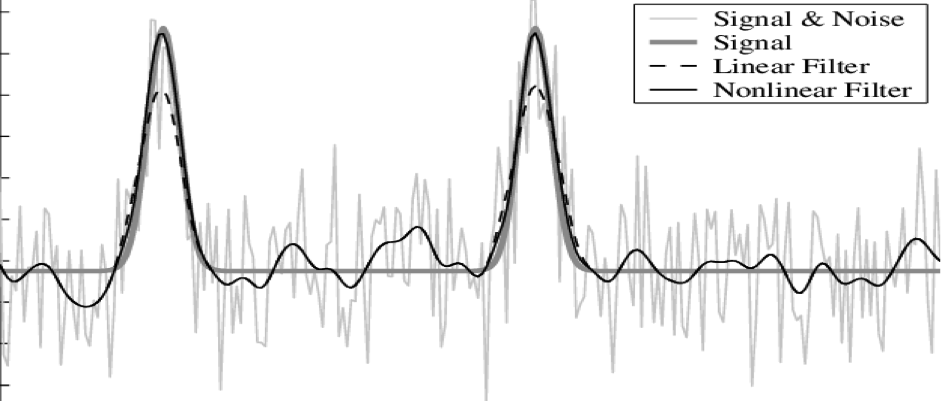
Fig.1 Signal with noise and with filter
In the field of electronics processing signals, signals are processed in a frequency-dependent manner by filters. Passive components like inductors and capacitors have impedances in their nature. The basic concept of filters can be explained by examining the frequency-dependent nature of passive components.
There are many practical applications of filters. At high frequencies, a single pole low pass filter gives stability to a system by rolling off the gain.
DC offset can be blocked in single supply circuits or high gain amplifiers using a single-pole, high pass filter. There are many applications of filters, such as separating signals and attenuating the unwanted frequencies components. For example, in radio communication, an attenuating signal is passed through typically with gain. The effect of aliases can also be eliminated by using filters in the A/D system in the data conversion. Filters can be used to reconstruct the output signal of D/A and can smooth a signal when removing higher frequency components like the sampling frequency and generated harmonics.
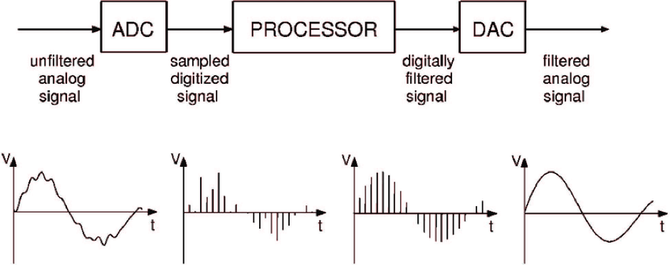
Fig.2 A/D & D/A with filtered signal.
For the ideal filter, the amplitude response will be unity or fixed gain for the frequencies of interest (pass band frequency) and zero everywhere else (stop band frequency). The frequency at which the response changes from the pass band to the stop band is called the cut-off frequency.
Features of hardware filters include:
- It can be implemented using only passive components like resistors and capacitors or inductors and capacitor.
- It can be designed of many orders as per the signal filtering requirement.
- Simple to analyze. No software needed to see the response.
- Can be used in many fields like telecommunication, analog signals, data acquisition, etc.
- Power supply noise reduction or filtration.
The electronics filter is the circuit that passes some frequency components in the circuit and rejects or attenuates all other frequency components. Based on the frequency band which is being passed by the filter, filters can be classified into four different types.
Low Pass Filter
An ideal low pass filter has low frequencies in the pass band and higher frequencies in the stop band. Active and passive components available in the low pass filter attenuates high-frequency components from the signal passing through it. For example, an electronics guitar has a tone knob fitted with a low pass filter to reduce the treble in the sound.
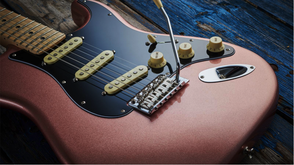
Fig.3 Electronic guitar tone knob.
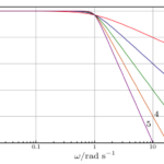
The below figure shows the frequency response of an ideal low pass filter.
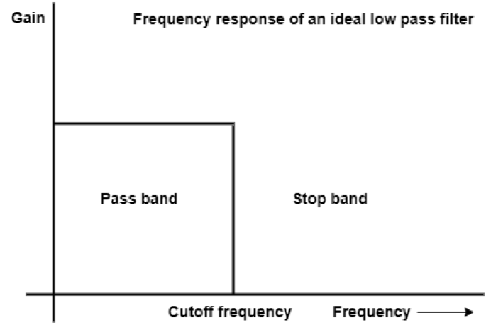
Fig. 4 Frequency of Ideal Low pass Filter
High pass filter
An ideal high pass filter has high frequencies in the pass band and low frequencies in the stop band. Active and passive components available in the high pass filter attenuate low-frequency components from the signal passing through it. For example, in audio signal recording, a high filter is used to eliminate the DC offset from the audio.
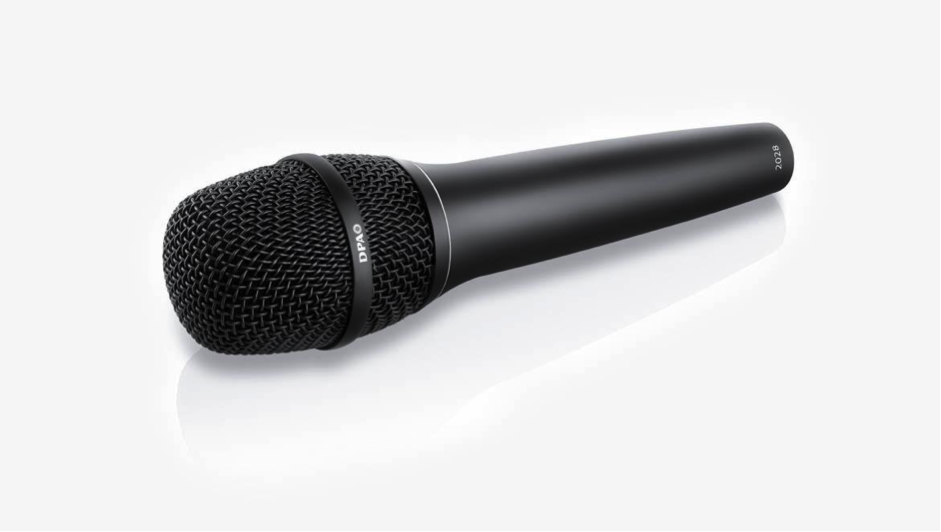
Fig.5 Mic
The below figure shows the frequency response of an ideal high pass filter.
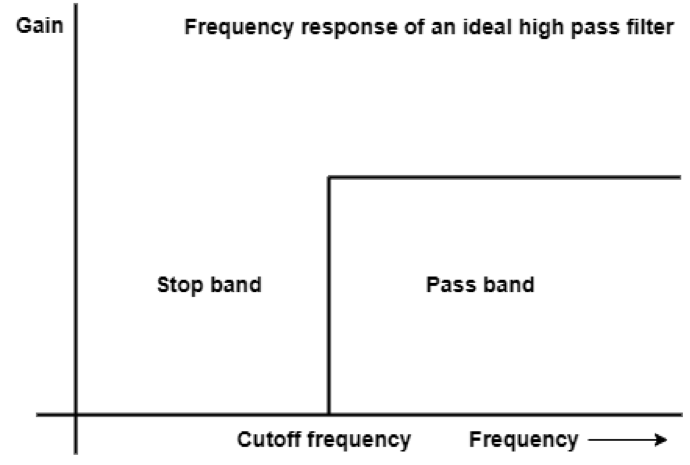
Fig.6 Frequency for high pass filter
Band pass filter
A band pass filter is a filter that has two transition points—one from stop band to pass band and the second is pass band to stop band. That means this filter has two cutoff frequencies in its frequency response. The filter passes a set of frequencies that comes under the pass band region. For example, in wireless communication (RF communication), a band pass filter is used to support a frequency band.
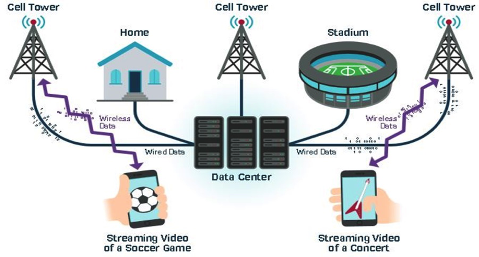
Fig.7 RF communication system
The below figure shows the frequency response of an ideal band pass filter.
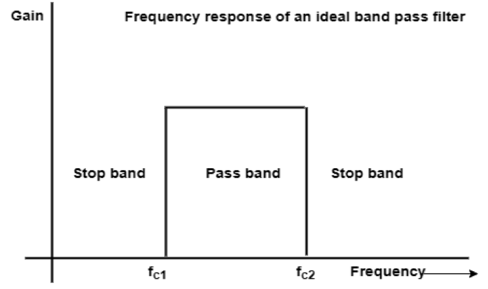
Fig. 8 Band Pass Filter Frequency
Band reject or notch filter
A band reject filter is a filter that attenuates a frequency band that comes under that stop band area. Like the band pass filter, it also has two transition points or cut-off frequencies. This filter is also called a notch filter and is used to remove a particular frequency from the signal passing through the band reject filter. For example, in the audio system band reject filter is used to remove interfering power line hum of a particular frequency such as 50Hz in India.

Fig. 9 Frequency response of ideal band reject filter
A practical filter has five parameters and typically exhibit one or more variables. The parameters:
- The cutoff frequency is the frequency at which the filter response leaves the pass band.
- The stop band frequency is the frequency at which the minimum attenuation is reached in the stop band.
- The pass band ripple is the variation in the filter response in the pass band.
- The sharp angle of the filter is defined as the order (M) of the filter.
- The number of poles in the transfer function is also called the order of the filter. A pole is a root of the denominator of the transfer function, and a zero is a root of the numerator of the transfer function.
It is not necessary that all filters will have these features. For example, if there are no zeros in the transfer function (all pole configurations), there will be no ripple in the stop band. Butterworth and Bessel filters are all pole filters that have no ripple in the pass band.
If you are designing an antialiasing filter for an ADC, then you will have to know the cutoff frequency (maximum frequency you want to pass), the stop band frequency, and the maximum attenuation required. From there, you can go for other parameters such as filter order, f0, and Q. These parameters will be discussed in the next article.
You may also like:
Filed Under: Featured Contributions, Hardware Filters, Tutorials

Questions related to this article?
👉Ask and discuss on Electro-Tech-Online.com and EDAboard.com forums.
Tell Us What You Think!!
You must be logged in to post a comment.