Engineers Garage

  • Electronic Projects & Tutorials
    • Electronic Projects
      • Arduino Projects
      • AVR
      • Raspberry pi
      • ESP8266
      • BeagleBone
      • 8051 Microcontroller
      • ARM
      • PIC Microcontroller
      • STM32
    • Tutorials
      • Audio Electronics
      • Battery Management
      • Brainwave
      • Electric Vehicles
      • EMI/EMC/RFI
      • Hardware Filters
      • IoT tutorials
      • Power Tutorials
      • Python
      • Sensors
      • USB
      • VHDL
    • Circuit Design
    • Project Videos
    • Components
  • Articles
    • Tech Articles
    • Insight
    • Invention Stories
    • How to
    • What Is
  • News
    • Electronic Product News
    • Business News
    • Company/Start-up News
    • DIY Reviews
    • Guest Post
  • Forums
    • EDABoard.com
    • Electro-Tech-Online
    • EG Forum Archive
  • DigiKey Store
    • Cables, Wires
    • Connectors, Interconnect
    • Discrete
    • Electromechanical
    • Embedded Computers
    • Enclosures, Hardware, Office
    • Integrated Circuits (ICs)
    • Isolators
    • LED/Optoelectronics
    • Passive
    • Power, Circuit Protection
    • Programmers
    • RF, Wireless
    • Semiconductors
    • Sensors, Transducers
    • Test Products
    • Tools
  • Learn
    • eBooks/Tech Tips
    • Design Guides
    • Learning Center
    • Tech Toolboxes
    • Webinars & Digital Events
  • Resources
    • Digital Issues
    • EE Training Days
    • LEAP Awards
    • Podcasts
    • Webinars / Digital Events
    • White Papers
    • Engineering Diversity & Inclusion
    • DesignFast
  • Guest Post Guidelines
  • Advertise
  • Subscribe

Two Way Traffic Light

By Anjali Sethiya April 21, 2008


This two way traffic light project described below is a small model of traffic light which we daily see in our life on street. With this circuit you can control two way traffics. There will be lights on both sides, like there is red light on one side and green light will be present aautomatically on another side. It will also have yellow light to alert the passengers or drivers that now there signal are going to open.

This circuit is based on three IC so before understanding the circuit let’s understand the working of individual IC.

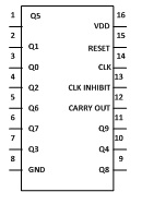
1. IC1 used is 4017– CD4017 is a 16 pin CMOS decade counter/ Divider.  It take clock signal from the clock input and turn on the 10 output in sequence, each time when it receives clock input pulses. It is the most popular IC and extremely useful in various project like Light Chaser, Matrix Die. It is also useful in many applications like Binary counter/decoder, frequency division, divide by N counting, Alarm system, Automotive etc.

It has 3 input and 10 output pins and one is ground pin and another is used for power supply and one is Carry out pin. Pin diagram of CD4017 is shown below-

Two Way Traffic Light

1. Input pin-

a. Reset pin (pin 15) – It is used to reset the counter to zero. If you want the counter to count up to third output then connect the fourth output to pin 15. Now after every third output it will automatically starts counting from zero.

b. Clock pin (pin14) – Whenever pin 14 goes high it will provide you the output. Like for first clock pulse pin 3 will provide you output similarly for next pulse pin 2 will provide output and so on. After 10 pulse it will again start from Q0 output.

c. Clock Inhibit pin (pin 13) – It is used to switch the counter “on” and “off”. When you want to switch off the counter then pin 13 should be high. If it is high it will ignore the clock pulse no matter how many times you press the switch means the count will not advance. In our circuit we have ground the pin 13.

2. Output pin (pin Q0- Q9) – It is used to receive the output in sequential manner. Like for first pulse pin 3 will provide you the output and so on.

3. Ground pin (pin 8) and Supply pin (pin 16) – It is used to provide ground and power supply to the IC for its working.

4. Carry out pin (pin 12) – It is used to connect one or more CD4017 IC’s. Like if you want to add one more CD4017 IC then connect Pin 12 to Clock input of its successor. The carry pin of first CD4017 is connected to clock input of second and the carry pin of second is connected to the clock input of third and so on. In our circuit we have used only one IC that’s why we have left this pin.

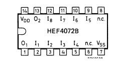
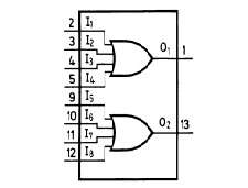
2. IC2 used is 4072– 4072 is a dual 4 input OR gate. Output of OR gate goes high when any of the input goes high and if all input is low then output is also low. 4072 is a 14 pin IC and contain 2 individual OR gate on a single IC. First gate include pin 2, 3, 4, 5 as input pin and pin 1 as output pin. And in second gate pin 9, 10, 11, 12 are output pin and 13 is output pin. Following figure shows the pin diagram and functional diagram of 4072 IC.

Two Way Traffic LightTwo Way Traffic Light

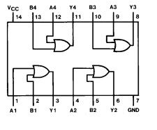
3. IC3 used is 7432– 7432 is a quad 2 input OR gate. In this also output goes high when any of the input is high and goes low when all inputs are low. 7432 contains 4 individual OR gate on single IC. In our circuit we are utilizing only 2 gates. Following figure shows the functional diagram of 7432 IC.

Two Way Traffic Light

 Working 

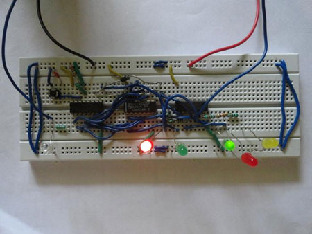
Working of Two Way Traffic Light Circuit

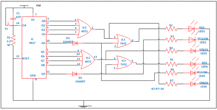
First of all make the connections as shown in circuit diagram.  Now provide power supply. In this circuit we are providing input signal to IC1 that is 4017 with the help of switch. So we are manually providing the input to our traffic light you can also use a 555 timer or logic gate IC which will automatically provide signals to on the decade counter/ divider IC4017. When you press the switch S1 counter starts from zero and it advances one each time whenever pin 14 receives a positive pulse. When switch is pressed first time output pin 3 of IC1 goes high. This high is provided to pin 2 of IC2 and from truth table of 4072 IC, if any of the input is high it will provide you the high output. Because of this pin 1 of IC2 become high and Green LED6 will glow. Similarly this high is also provided to pin 1 of IC3 therefore from truth table its output also goes high indicated by glowing of RED LED1. So at one way RED light is there and on another way Green light is on.

When you press the switch next time pin 2 of IC1 goes high. It makes pin 1 and pin 3 of IC2 and IC3  high and RED LED1 and Green LED 6 continuous to glow. Similar phenomenon happens when you press the switch third and fourth time. Because it is making the pin 1 and pin 3 of IC2 and IC3 to go high (this can be verified with the help of truth table). Now when you press the switch for fifth time pin 10 of IC1 goes high and this will make all input (2, 3, 4 & 5) of IC2 low because of that Green LED 6 stop glowing. And Yellow LED5 connected to Diode D1 start glowing. And pin 3 of IC3 is high and Red LED1 continuous to glow. This shows that now another way is going to open.

Now when you press the switch for sixth time pin 1 of IC1 goes high. Which will make the pin 13 of IC1 goes high this will glow the Green LED 3. It will also makes the pin 4 of IC3 high and because of this, pin 6 of IC3 also high and Red LED 4  also glow. This indicates that one side we have Red light and another side we have Green light. When you press the switch next time pin 5 of IC1 goes high. This makes pin 10 and pin 6 of IC2 and IC3 high and Green LED3 and Red LED 4 continuous to glow. Similar phenomenon happens when you press the switch eighth and ninth time. Because it is making the pin 13 and pin 6 of IC2 and IC3 to go high (this can be verified with the help of truth table).

Now when you press the switch for tenth time pin 11 of IC1 goes high and this will make all input (9, 10, 11 & 12) of IC2 low because of that Green LED 6 stop glowing. And Yellow LED2 connected to Diode D2 start glowing. And pin 6 of IC3 is high and Red LED4 continuous to glow. This shows that that now another way is going to open. Therefore you can now see that at a time only one way is open and another have to wait for light to turn Green.


Two Way Traffic Light


Circuit Diagrams

2-Way-traffic-light


Filed Under: Electronic Projects
Tagged With: circuit, traffic light
 

Next Article

← Previous Article
Next Article →

Questions related to this article?
👉Ask and discuss on EDAboard.com and Electro-Tech-Online.com forums.


Tell Us What You Think!! Cancel reply

You must be logged in to post a comment.

EE TECH TOOLBOX

“ee
Tech Toolbox: 5G Technology
This Tech Toolbox covers the basics of 5G technology plus a story about how engineers designed and built a prototype DSL router mostly from old cellphone parts. Download this first 5G/wired/wireless communications Tech Toolbox to learn more!

EE Learning Center

EE Learning Center
“engineers
EXPAND YOUR KNOWLEDGE AND STAY CONNECTED
Get the latest info on technologies, tools and strategies for EE professionals.

HAVE A QUESTION?

Have a technical question about an article or other engineering questions? Check out our engineering forums EDABoard.com and Electro-Tech-Online.com where you can get those questions asked and answered by your peers!


RSS EDABOARD.com Discussions

  • Exporting sensor readings as data...
  • problem connecting to my xilinx device VIA global IP
  • Output Stage Microwave Device Selection
  • lumped port or wave port in ansys hfss for my on-chip spiral inductor ??
  • NXP library issue in awr

RSS Electro-Tech-Online.com Discussions

  • using a RTC in SF basic
  • What is correct names for GOOD user friendly circuit drawing program?
  • Is AI making embedded software developers more productive?
  • Why can't I breadboard this oscillator?
  • Parts required for a personal project

Featured – RPi Python Programming (27 Part)

  • RPi Python Programming 21: The SIM900A AT commands
  • RPi Python Programming 22: Calls & SMS using a SIM900A GSM-GPRS modem
  • RPi Python Programming 23: Interfacing a NEO-6MV2 GPS module with Raspberry Pi
  • RPi Python Programming 24: I2C explained
  • RPi Python Programming 25 – Synchronous serial communication in Raspberry Pi using I2C protocol
  • RPi Python Programming 26 – Interfacing ADXL345 accelerometer sensor with Raspberry Pi

Recent Articles

  • GigaDevice launches GD32C231 MCU series with 48MHz Cortex-M23 core and 64KB Flash
  • Advanced Energy releases 425 W CF-rated medical power supply in 3.5 x 6 x 1.5-inch format”
  • LEM combines shunt and Hall effect sensing in 2000 A current measurement unit
  • What is AWS IoT Core and when should you use it?
  • AC-DC power supply extends voltage range to 800 V DC

EE ENGINEERING TRAINING DAYS

engineering

Submit a Guest Post

submit a guest post
Engineers Garage
  • Analog IC TIps
  • Connector Tips
  • Battery Power Tips
  • DesignFast
  • EDABoard Forums
  • EE World Online
  • Electro-Tech-Online Forums
  • EV Engineering
  • Microcontroller Tips
  • Power Electronic Tips
  • Sensor Tips
  • Test and Measurement Tips
  • 5G Technology World
  • Subscribe to our newsletter
  • About Us
  • Contact Us
  • Advertise

Copyright © 2025 WTWH Media LLC. All Rights Reserved. The material on this site may not be reproduced, distributed, transmitted, cached or otherwise used, except with the prior written permission of WTWH Media
Privacy Policy

Search Engineers Garage

  • Electronic Projects & Tutorials
    • Electronic Projects
      • Arduino Projects
      • AVR
      • Raspberry pi
      • ESP8266
      • BeagleBone
      • 8051 Microcontroller
      • ARM
      • PIC Microcontroller
      • STM32
    • Tutorials
      • Audio Electronics
      • Battery Management
      • Brainwave
      • Electric Vehicles
      • EMI/EMC/RFI
      • Hardware Filters
      • IoT tutorials
      • Power Tutorials
      • Python
      • Sensors
      • USB
      • VHDL
    • Circuit Design
    • Project Videos
    • Components
  • Articles
    • Tech Articles
    • Insight
    • Invention Stories
    • How to
    • What Is
  • News
    • Electronic Product News
    • Business News
    • Company/Start-up News
    • DIY Reviews
    • Guest Post
  • Forums
    • EDABoard.com
    • Electro-Tech-Online
    • EG Forum Archive
  • DigiKey Store
    • Cables, Wires
    • Connectors, Interconnect
    • Discrete
    • Electromechanical
    • Embedded Computers
    • Enclosures, Hardware, Office
    • Integrated Circuits (ICs)
    • Isolators
    • LED/Optoelectronics
    • Passive
    • Power, Circuit Protection
    • Programmers
    • RF, Wireless
    • Semiconductors
    • Sensors, Transducers
    • Test Products
    • Tools
  • Learn
    • eBooks/Tech Tips
    • Design Guides
    • Learning Center
    • Tech Toolboxes
    • Webinars & Digital Events
  • Resources
    • Digital Issues
    • EE Training Days
    • LEAP Awards
    • Podcasts
    • Webinars / Digital Events
    • White Papers
    • Engineering Diversity & Inclusion
    • DesignFast
  • Guest Post Guidelines
  • Advertise
  • Subscribe