Today we are going to interface a very interesting sensor with NRF module.
Have you ever heard bats communicating with each other? We can’t hear them because they use ultrasonic frequency to communicate with each other. Ultrasonic frequencies cannot be heard by human ears. Human can only hear sound between 20 – 20 KHz frequency whereas ultrasonic frequency lies above 20 KHz and expands up to several GHz.
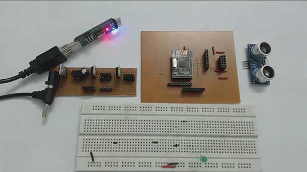
Fig. 1: Prototype of NRF24LE1 Interfacing with Ultrasonic Sensor
The ultrasonic waves have different travelling speed in air, liquid and gases. In air they usually travel at 340 m/s. They have the tendency to get reflected from a solid surface. Due to this functionality they are used in distance measurement. If the time between transmission and reception is known then the distance of the solid surface form the transmitter can be calculated.
We will use HCSR04 ultrasonic sensor that has transmitter, receiver and control circuit inbuilt. We will interface this sensor with NRF24LE1 using input/output pins.
HCSR04 has 4 pins:
1. VCC – 5V
2. Trig – Trigger input pin
3. Echo – Output pin
4. Gnd – Ground
Some specifications of this sensor are:
· 2cm – 400 cm distance measurement range
· Working frequency – 40Khz
· Uses 10 uS (micro second) Trigger pulse.
· Transmits eight 40khz pulses when triggered
· Receives echo and outputs high pulse with range in proportion to distance.
· 60 mS of delay should be given between next triggering.
Calculation of distance

Fig. 2: Image of NRF24LE1 Interfacing with Ultrasonic Sensor
There are two ways to measure distance:
1. First determine the time between transmission and reception of echo. Then use the formula = Time * velocity / 2. In air velocity is 340 m/s.
2. Calculate the time for which the output pin of sensor is high. Then, use the predetermined formula, distance in cm = time/58 or distance in inch = time/148. The time will be in uS.
We will be using the second method for calculation of distance.
Please make sure that you have read our previous articles on Timers and NRF24LE1.
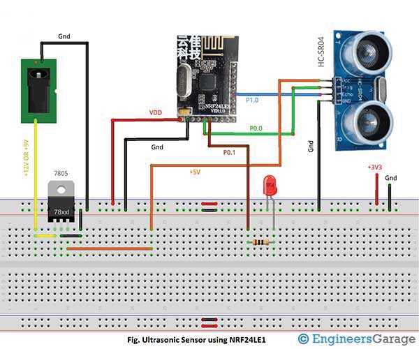
The NRF module will be used to trigger the senor with a 10 us pulse. After triggering, the sensor will send 40 KHz signal and will wait for the echo. If echo is received it will output a high pulse. This high pulse will have a width range in proportion to distance.
In NRF, the pin0 of port0 or P00 is used as output pin for triggering the sensor while pin 1 of port0 or P01 is used as input pin to receive the high pulse from sensor.
We are using Timer0 to measure time period for which the output pin remains high. Timer0 is initialized in Mode1 that is 16-bit mode. This means that we can measure time up to (0.75 * 65536) = 49152 uS. To calculate the time measured by timer0 we use, time = (timer0 register value * 0.75) uS. To calculate distance of solid object we can use, distance in cm = time/ 58.
We have written the code for you to understand the working.
You may also like:
Project Source Code
###
//Program to/* Copyright (c) 2009 Nordic Semiconductor. All Rights Reserved.** The information contained herein is confidential property of Nordic* Semiconductor ASA.Terms and conditions of usage are described in detail* in NORDIC SEMICONDUCTOR STANDARD SOFTWARE LICENSE AGREEMENT.** Licensees are granted free, non-transferable use of the information. NO* WARRENTY of ANY KIND is provided. This heading must NOT be removed from* the file.** $LastChangedRevision: 133 $*/#include// standard I/O library #include "nrf24le1.h" // I/O header file for NRF24LE1#include "hal_uart.h" // library containing serial communication functions#include "hal_clk.h" // library containing clock functions#include// standard library #include// library containing string functions #include// library containing maths functions #include "hal_delay.h" // header file containing delay functionssfr16 DPTR = 0X82; // functional register to hold value// Repeated putchar to print a stringvoid putstring(char *s){while(*s != 0)putchar(*s++);}// function to convert integer into string arrayvoid itoa(int num, char* str){int i= 0, count = 0;int temp = num;if(num == 0){str[i++] = '0';str[i] = '';return;}while(temp != 0){int rem = temp % 10;temp = temp/10;count ++;}str[count --] = '';while(num != 0){int rem = num % 10;str[count --] = (rem > 9) ? (rem - 10) + '1' : rem + '0';num = num/10;}return;}###
Circuit Diagrams
Project Video
Filed Under: Tutorials
Filed Under: Tutorials





Questions related to this article?
👉Ask and discuss on Electro-Tech-Online.com and EDAboard.com forums.
Tell Us What You Think!!
You must be logged in to post a comment.