Engineers Garage

  • Electronics Projects and Tutorials
    • Electronic Projects
      • Arduino Projects
      • AVR
      • Raspberry pi
      • ESP8266
      • BeagleBone
      • 8051 Microcontroller
      • ARM
      • PIC Microcontroller
      • STM32
    • Tutorials
      • Audio Electronics
      • Battery Management
      • Brainwave
      • Electric Vehicles
      • EMI/EMC/RFI
      • Hardware Filters
      • IoT tutorials
      • Power Tutorials
      • Python
      • Sensors
      • USB
      • VHDL
    • Circuit Design
    • Project Videos
    • Components
  • Articles
    • Tech Articles
    • Insight
    • Invention Stories
    • How to
    • What Is
  • News
    • Electronic Product News
    • Business News
    • Company/Start-up News
    • DIY Reviews
    • Guest Post
  • Forums
    • EDABoard.com
    • Electro-Tech-Online
    • EG Forum Archive
  • DigiKey Store
    • Cables, Wires
    • Connectors, Interconnect
    • Discrete
    • Electromechanical
    • Embedded Computers
    • Enclosures, Hardware, Office
    • Integrated Circuits (ICs)
    • Isolators
    • LED/Optoelectronics
    • Passive
    • Power, Circuit Protection
    • Programmers
    • RF, Wireless
    • Semiconductors
    • Sensors, Transducers
    • Test Products
    • Tools
  • Learn
    • eBooks/Tech Tips
    • Design Guides
    • Learning Center
    • Tech Toolboxes
    • Webinars & Digital Events
  • Resources
    • Digital Issues
    • EE Training Days
    • LEAP Awards
    • Podcasts
    • Webinars / Digital Events
    • White Papers
    • Engineering Diversity & Inclusion
    • DesignFast
  • Guest Post Guidelines
  • Advertise
  • Subscribe

Understanding NeuroSky EEG Chip in Detail (Part 2/13)

By Arpit jain June 30, 2022

Now that we know the basics of Brainwaves and the sensor on which we are working, it’s time to learn about the brain of this brain wave sensor. The main part of any device is its processing part and in the case of Mindflex Sensor, it’s the NeuroSky EEG Chip.

Let’s move on to the details so as to know what the chip contains and how does it work.

Some details from the information provided by the company:

1. It is from the Product Family, ThinkGear AM, where A means ASIC and M means Module.

2. Model Number of the Chip is TGAM1, Revision Number 2.3.

3. Dimension of the Module is 29.9mm X 15.2mm X 2.5mm (1.1 in X 0.60 in X 0.10 in).

4. Module weight is 130 mg (0.0045 ounces).

5. Operating Voltage of this Module is 2.97 V – 3.63V

6. Maximum Input Noise, the module can filter is 10mV peak to peak. We will later measure our noise and will make sure that the noise in within the module range for optimum results.

7. Maximum Power Consumption of the module is 15mA @3.3V. We will check these values with a multimeter and will measure each parameter. It will be fun to check these values by our own.

8. ESD Protection of the device is 4kV for the Contact Discharge and 8kV for the air discharge. It’s important to note that Electro Static Discharge is the flow of electricity between two charged objects caused by contact, dielectric breakdown or electric shock. It is mainly caused by a static charge of two bodies. The static electricity can be built by induction ortribo charging (Certain material become electrically charged after they came into contact with different material)

9. The device can communicate serially with 9600, 1200, 57600 bps baud rate.  There are configuration pins by the help of which, we can change the baud rate. I will make sure I will cover this part later.

10.  Also, this TGAM1 chip can handle only 1 EEG input and we also need to process just one EEG channel, so it is apt to use this Chip.

Here is the PIN diagram of this TGAM1 (NeuroSky Chip).

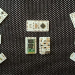
This is the view which we see when we have opened the mindflex headband.

Here, by seeing these two images, we can observe that the 5 pins at the right side of pic1 are the five pins on the left side of Pic2.

Let me tell you in brief about the pins of this chip.

In P3

1. 1 is GND “-”
2. 2 is VCC “+”
3. 3 is RXD “R”
4. 4 is TXD “T”

In P4

1. 1 is VCC “+”
2. 2 is GND “-”

In P1

1. 1 is EEG Electrode “EEG”
2. 2 is EEG Shield
3. 3 is Ground Electrode
4. 4 is Reference Shield
5. 5 is Reference Electrode “RF”

Labels marks “” are labeled on PCB.

PIN Diagram of NeroSky Chip

Fig. 1: PIN Diagram of NeroSky Chip

Gaphic Image Showing Configuration of NueroSky Chip

Fig. 2: Graphic Image Showing Configuration of NueroSky Chip

Now let’s see how we can change the serial transmission speed of the NeuroSky Chip and its data content.  You may find this chip in some other Brain Headband and if you want to change the transmission speed or data content then this article is for you.

Well, ThinkGear sends the following packets, usually serially. The codes that may appear in the packets are:

1. 0x02  – Poor Quality
2. 0x04 – eSense Attention (0-100)
3. 0x05 – eSense Meditation (0 -100)
4. 0x80 – 10 bit Raw EEG
5. 0x83 – EEG Powers

TGAM1 supports following command bytes:

1. Page0(oxo_) :STANDARD/ASIC CONFIG COMMANDS
2. 0x00: 9600 baud rate with normal output mode
3. 0x01: 1200 baud rate with normal output mode
4. 0x02: 57.6k baud rate with normal and raw output mode

These commands can change the baud rate and data content of the NeuroSky EEG chip.

Configuration

TGAM1 has built-in configuration pad which can be used to change the default settings. There are two types of default setting that can be changed, namely baud rate and data content. The configuration pads are located on the back side of the TGAM1 chip. The B0 is used to configure the baud rate and B1 is used to configure the data content. The M pad is used to configure the notch filter frequency.

Image Giving A Side View of NeuroSky EEG Chip

Fig. 3: Image showing a side view of NeuroSky EEG Chip

Table Listing Configuration Parameters of NeuroSky EEG Chip

Fig. 4: Table listing configuration parameters of NeuroSky EEG Chip

In the normal output, the chip transmits poor quality value, EEG value, Attention Value and Meditation Value.

In the Default mode, the B0 and B1 are connected to ground to communicate at 9600bps with normal output.

We can also change this configuration by sending commands serially to the chip. I have discussed earlier the commands which TGAM supports.

So, by sending command 0x01, 0x02, 0x00 we can change the configuration serially.  But once the system is reset, it will return to the hardware reset and will continue in the configuration set by B0 and B1.

Now, the TGAM has notch filters to reduce the outside noise. The notch filter frequency can be set by the M pin. It is usually used to reduce the 50Hz or 60 Hz noise of the environment. In our previous articles also, we have seen that there was a noise coming from the environment of 50Hz in India. This is because the supply which we get from the Govt is of 50Hz and magnetic field of 50Hz floats in the environment. This is the reason there is a sense of this field in the brain wave.

To remove this extra signal from our brain wave, TGAM1 has notch filters. The M pin is to configure this to 50Hz or 60Hz. If the M pin is connected to Vcc than it is working at 60Hz and if the M pic is connected to Ground, then it is working at 50Hz.

By default setting of the TGAM1 pins is 9600 bps with normal output and notch filer of 60Hz frequency. I hope now if you ever see this TGAM1 chip then you can work on its configuration and can do your desired task.

How does it work?

After going through the components and configuration of the EEG chip, it’s important to get acquainted with its working so as to extinguish the fire of exploration in our mind. So let’s get started with that.

Image showing Top View of NeuroSky EEG Chip

Fig. 5: Image showing top view of NeuroSky EEG Chip

Here is my detailed assumption how this chip will be working. I am not pretty sure about it but this information has been gathered from various sources.

The Chip has 5 inputs including EEG, its shield, ground, reference. Now the EEG electrode is directly connected with the EEG pin with a shield. The reference of this data is the reference electrode which is finally connected to our ear. Now the TGAM1 chip has one processor with filters. These filters are to filter noise and to separate different brain wave type.

Let us say an EEG signal from our brain enters the TGAM1 chip. This signal first enters into a filter which separates all the signals with more than 100Hz frequency. As most probably the highest frequency wave i.e. Gamma wave is up to 100 Hz. After that according to the M pin configuration, extra signals of frequency 50Hz or 60Hz are removed. Now we have a signal with a frequency ranging from 0.3Hz to 100 Hz. Now filters will divide it according to the Brainwave type. For ex, from 3Hz to 7Hz waves are separated differently as compared to those from 7Hz to 13Hz and so on.

Now, these signals are sampled at the rate of 512 Hz and later are sent to the ADC with the 12-bit resolution. This finally ends up getting a digital value for each separate Brainwave types. Now by many digital values of a single Brainwave type, power FFT is calculated by the processor. After getting the power FFT values of all the Brainwave Types the processor looks for the configuration pins. We have recently discussed the configuration pins. Now after the configuration pins, the processor output the digital FFT values for each Brainwave type serially via the Tx pin at the baud rate set by the configuration pin. The default value is 9600 with normal output.

The mindflex board receives these serial values and then does its own calculation for transmitting this signal wirelessly. This sums up the NeuroSky chip EEG details.  Stay tuned for more information on the experimentation of brain waves.

You may also like:


  • What are the top development boards for AI and ML?

  • What are LoRa gateways and what types are available?

  • What are the top tools for developing embedded software?

  • Introduction to Brain Waves & its Types (Part 1/13)

  • How To Use MikroC Pro For PIC16F877A Microcontroller?

  • BITalino: What if you could make your own body signals…

Filed Under: Brainwave, Tech Articles, Tutorials


Next Article

← Previous Article
Next Article →

Questions related to this article?
👉Ask and discuss on Electro-Tech-Online.com and EDAboard.com forums.


Tell Us What You Think!! Cancel reply

You must be logged in to post a comment.

EE TECH TOOLBOX

“ee
Tech Toolbox: Internet of Things
Explore practical strategies for minimizing attack surfaces, managing memory efficiently, and securing firmware. Download now to ensure your IoT implementations remain secure, efficient, and future-ready.

EE Learning Center

EE Learning Center
“engineers
EXPAND YOUR KNOWLEDGE AND STAY CONNECTED
Get the latest info on technologies, tools and strategies for EE professionals.

HAVE A QUESTION?

Have a technical question about an article or other engineering questions? Check out our engineering forums EDABoard.com and Electro-Tech-Online.com where you can get those questions asked and answered by your peers!


RSS EDABOARD.com Discussions

  • Colpitts oscillator
  • problem identifying pin purpose on PMA5-83-2WC+ amplifier
  • Voltage Regulator Sizing Question
  • Genetic algorithm code in matlab for cost optimization
  • SDR as wideband spectrum analyzer

RSS Electro-Tech-Online.com Discussions

  • Electronic board faulty?!?
  • Can I use this charger in every country?
  • using a RTC in SF basic
  • An Update On Tarrifs
  • Wish to buy Battery, Charger and Buck converter for 12V , 2A router

Featured – Designing of Audio Amplifiers part 9 series

  • Basics of Audio Amplifier – 1/9
  • Designing 250 Milli Watt Audio Power Amplifier – 2/9
  • Designing 1 Watt Audio Power Amplifier – 3/9
  • Designing a Bass Boost Amplifier – 4/9
  • Designing a 6 Watt Car Audio Amplifier – 5/9
  • Design a low power amplifier for headphones- 6/9

Recent Articles

  • Fischer connector system adds ratchet locking system designed for 300g shock resistance
  • Littelfuse introduces tactile switch with enhanced bracket peg design for mounting strength
  • Infineon releases GaN switch with monolithic bidirectional design
  • Sienna Semiconductor data converters feature sample rates from 20 to 250 Msps
  • Delta’s 5,500 W power supplies achieve 97.5% energy efficiency for AI servers

EE ENGINEERING TRAINING DAYS

engineering

Submit a Guest Post

submit a guest post
Engineers Garage
  • Analog IC TIps
  • Connector Tips
  • Battery Power Tips
  • DesignFast
  • EDABoard Forums
  • EE World Online
  • Electro-Tech-Online Forums
  • EV Engineering
  • Microcontroller Tips
  • Power Electronic Tips
  • Sensor Tips
  • Test and Measurement Tips
  • 5G Technology World
  • Subscribe to our newsletter
  • About Us
  • Contact Us
  • Advertise

Copyright © 2025 WTWH Media LLC. All Rights Reserved. The material on this site may not be reproduced, distributed, transmitted, cached or otherwise used, except with the prior written permission of WTWH Media
Privacy Policy

Search Engineers Garage

  • Electronics Projects and Tutorials
    • Electronic Projects
      • Arduino Projects
      • AVR
      • Raspberry pi
      • ESP8266
      • BeagleBone
      • 8051 Microcontroller
      • ARM
      • PIC Microcontroller
      • STM32
    • Tutorials
      • Audio Electronics
      • Battery Management
      • Brainwave
      • Electric Vehicles
      • EMI/EMC/RFI
      • Hardware Filters
      • IoT tutorials
      • Power Tutorials
      • Python
      • Sensors
      • USB
      • VHDL
    • Circuit Design
    • Project Videos
    • Components
  • Articles
    • Tech Articles
    • Insight
    • Invention Stories
    • How to
    • What Is
  • News
    • Electronic Product News
    • Business News
    • Company/Start-up News
    • DIY Reviews
    • Guest Post
  • Forums
    • EDABoard.com
    • Electro-Tech-Online
    • EG Forum Archive
  • DigiKey Store
    • Cables, Wires
    • Connectors, Interconnect
    • Discrete
    • Electromechanical
    • Embedded Computers
    • Enclosures, Hardware, Office
    • Integrated Circuits (ICs)
    • Isolators
    • LED/Optoelectronics
    • Passive
    • Power, Circuit Protection
    • Programmers
    • RF, Wireless
    • Semiconductors
    • Sensors, Transducers
    • Test Products
    • Tools
  • Learn
    • eBooks/Tech Tips
    • Design Guides
    • Learning Center
    • Tech Toolboxes
    • Webinars & Digital Events
  • Resources
    • Digital Issues
    • EE Training Days
    • LEAP Awards
    • Podcasts
    • Webinars / Digital Events
    • White Papers
    • Engineering Diversity & Inclusion
    • DesignFast
  • Guest Post Guidelines
  • Advertise
  • Subscribe