Engineers Garage

  • Electronics Projects and Tutorials
    • Electronic Projects
      • Arduino Projects
      • AVR
      • Raspberry pi
      • ESP8266
      • BeagleBone
      • 8051 Microcontroller
      • ARM
      • PIC Microcontroller
      • STM32
    • Tutorials
      • Audio Electronics
      • Battery Management
      • Brainwave
      • Electric Vehicles
      • EMI/EMC/RFI
      • Hardware Filters
      • IoT tutorials
      • Power Tutorials
      • Python
      • Sensors
      • USB
      • VHDL
    • Circuit Design
    • Project Videos
    • Components
  • Articles
    • Tech Articles
    • Insight
    • Invention Stories
    • How to
    • What Is
  • News
    • Electronic Product News
    • Business News
    • Company/Start-up News
    • DIY Reviews
    • Guest Post
  • Forums
    • EDABoard.com
    • Electro-Tech-Online
    • EG Forum Archive
  • DigiKey Store
    • Cables, Wires
    • Connectors, Interconnect
    • Discrete
    • Electromechanical
    • Embedded Computers
    • Enclosures, Hardware, Office
    • Integrated Circuits (ICs)
    • Isolators
    • LED/Optoelectronics
    • Passive
    • Power, Circuit Protection
    • Programmers
    • RF, Wireless
    • Semiconductors
    • Sensors, Transducers
    • Test Products
    • Tools
  • Learn
    • eBooks/Tech Tips
    • Design Guides
    • Learning Center
    • Tech Toolboxes
    • Webinars & Digital Events
  • Resources
    • Digital Issues
    • EE Training Days
    • LEAP Awards
    • Podcasts
    • Webinars / Digital Events
    • White Papers
    • Engineering Diversity & Inclusion
    • DesignFast
  • Guest Post Guidelines
  • Advertise
  • Subscribe

USB Protocol: Types of USB Packets and USB Transfers (Part 2/6)

By Amanpreet Singh September 28, 2024

After discussing the features and architecture of USB, let’s move on to its protocol. A USB interface has several layers of protocol. Most of the time the lower level layers are single handled by host controller IC while the end designer needs to work on higher level layers. Every communication protocol involves the exchange of packets. Same is the case with USB. These packets encapsulate information in a standard-defined organized manner. These packets generally contain information related to:

• Controlling the data exchange

• Data exchange in the form of actual payload

• Error detection and correction through status check up

USB Packet Fields

In USB the LSB of the packet is transmitted first. An USB packet contains different fields. They are:

• Sync: It is a mandatory field occurring at starting of the packet. This field synchronizes the clock of the receiver with the transmitter. For low and full speed mode, this field is 8 bytes long and for high speed mode it is 32 bytes long.

• PID: PID means Packet ID. It indicates the packet type that is being sent. This field is of 8 bits long. The upper four bits identifies the type of packet and lower four bits are bit-wise compliment of upper four bits. The lower four bits helps in detecting errors.
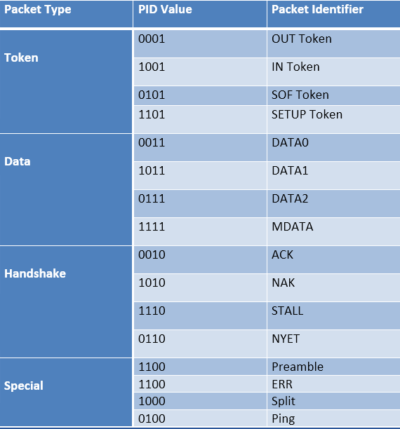
Table Listing USB Packet Fields

Fig. 1: Table Listing USB Packet Fields

• ADDR: This field contains the designation address of the USB device. It is of 7 bits, this means it can supports 27 ¬ = 127 devices.

• ENDP: This field specifies the endpoint number. It is of 4 bits, this means it can indicate 2¬¬4¬¬ ¬¬= 16 possible endpoints.

• CRC: CRC stands for Cyclic Redundancy Check. This field is used to check data in the packet for any error using CRC process

For token packets, 5-bit CRC is used and for data packets 16-bit CRC is used

• EOP: EOP stands for End of Packet. This field signals the data lines for Single Ended Zero(SE0) for approximately 2 bit times, followed by J state(idle state) for 1 bit time

Types of USB packets

Basically there are four types of data packets:

1. Token packets: These packets are only sent by host. The packet structure contains a PID byte, 11 bits of address and a 5-bit CRC. Types of token packets :

Image Showing Data Format of Token Packets

Fig. 2: Image showing Data Format of Token Packets

• In – This packet notifies the USB device that host wants to read information.
• Out – This packet notifies the USB device that host wants to write information.
• Setup – This packet is used to start the control transfer
With USB2.0, two more packets were added:
• Ping – Before sending OUT/DATA packet pair, this token asks the USB device if it is ready to receive OUT/DATA packet pair.
• Split – This token is used to communicate to a low/full speed device on a high speed bus

2. Data packets: Two types of data packets are there, Data0 and Data1. The packet structure contains a PID byte, data field and 16-bit CRC. The data field can carry 0- 1023 bytes of data. Data must be always sent in multiple of bytes.

Image Showing Data Format of Data Packets

 Fig. 3: Image showing data format of Data Packets

• For low speed devices, maximum data field is of 8bytes.
• For full speed devices, maximum data field is of 1023bytes.
• For high speed devices, maximum data field is of 1024bytes

After USB2.0, two more types were added Data2 and MData. They are only used in high speed transfer high bandwidth isochronous transfer when there is a need to transfer more than 1024 bytes at 8192 kB/s.

3. Handshake Packets: These packets are mostly sent in response to data packets. They simply consist of a PID byte. There are three types of handshake packets :

Image Showing Data Format of Handshake Packets

 Fig. 4: Image showing Data Format of Handshake Packets

• ACK – Acknowledgment for packet received
• NAK – indicating that packets cannot be temporarily received or send. Also used to indicate that there is no data to send
• STALL – indicating that the device is in error state and needs intervention from the host
With USB2.0, two more packets were added:
• NYET – indicating Split transaction is not yet complete.
• ERR – indicating Split transaction failed
4. Start of Frame packets (SOF): The SOF packet consists of an incrementing 11-bit frame number. On a full speed bus, this packet is sent by the host every 1ms and on a high speed bus every 125 us. This packet is used to synchronize isochronous transfer.
Image Showing Data Format of Start of Frame Packets (SOF)
Fig. 5: Image showing data Format of Start of Frame packets (SOF)

Transactions

A successful transaction consists of up-to three phases that occur in sequence. They are Token phase, Data phase and Handshake phase.

Block Diagram of USB Transaction

Fig. 6: Block Diagram of USB Transaction

These phases ensured secure transfer of data. There are three types of transactions :

Table Listing Types of USB Transactions

Fig. 7: Table Listing Types of USB Transactions

Types of USB Transfer

Types of USB Transfers

Table Listing Types of USB Transactions

Fig. 8: Table Listing Types of USB Transfers

USB currently supports four types of transfer modes. Each of them is designed to solve different purposes. They are :

1. Control Transfers

Control transfers are used to carry information related to configuration of the peripheral device. The host learns about the peripheral through this transfer. It also supports command and status type communication flow. The default control endpoint is always zero. It is the control endpoint which responds to host queries like Device Description through control transfer.

There are three stages in control transfer and each stage is made up of one or more transactions. They are:

• Setup stage – The control transfer always begin with this stage. In this, the host sends the query/request to the USB device (peripheral).

• Data stage – In this stage, several IN or OUT transactions are made. The Data packet contains the information related to request made in previous stage.

• Status stage – This stage uses on IN or OUT transaction. This stage always occurs in order to provide the status/result of the request made by host.

Control Transfers are supported by all speed modes. The maximum data payload size for data packet in data stage is different for each speed mode. For low speed devices, it is 8 bytes. For full speed devices it may be 8, 16, 32 or 64 bytes. For high speed devices, it is 64 bytes. These bytes do not include PID and CRC bit.

2. Bulk Transfers

Bulk Transfers are used to transfer large amount of data sequentially. They have no guaranteed bandwidth. The transfer takes place when there is some bandwidth left after allocating bandwidth to Control, Interrupt and Isochronous transfer. If there is no bandwidth available or the bus is busy, the transfer may take very long to complete.

Bulk transfers are unidirectional. These are only supported by Full Speed and High Speed devices. The maximum data payload size for data packet is different for each speed mode. For full speed devices it is 8, 16, 32 or 64 bytes. For high speed devices, it is up to 512 bytes. These bytes do not include PID and CRC bits.

3. Isochronous Transfers

Isochronous Transfer is used where data delivery at constant rate is important even if some data gets missed or corrupted. Guaranteed bandwidth is there for Isochronous Transfer but there is no guarantee for error free delivery. They are typically used to transmit time-sensitive information, like audio or video. There should not be any delay in data transmission for real time audio or video streaming; else it will result in glitches at output.

They are unidirectional and uses either IN or OUT transaction. A special feature of Isochronous Transfer is that, there is no handshake packet in transaction. These are only supported by Full and High Speed devices.

The maximum data payload size for data packet is different for each speed mode. For full speed devices it is up to 1023 bytes. For high speed devices, it is up to 1024 bytes. These bytes do not include PID and CRC bits.

4. Interrupt Transfers

Interrupt Transfer uses polling to check if there is any device which wants to transfer data. If the device does not have any data to send it responds with NAK. The polling is done on regular basis. Interrupt transfer is also used to transmit data to a device on scheduled basis. The device responds with NAK if it is not ready to accept data.

In this type of transfer, IN and OUT transactions are performed on regular scheduled basis. The maximum data payload size for Interrupt transfer is different for each speed mode. For low speed devices, it is up to 8 bytes. For full speed devices it is up to 64 bytes. For high speed devices, it is up to 1024 bytes. These bytes do not include PID and CRC bits.

Table Comparing Types of USB Transfers

Fig. 9: Table Comparing types of USB Transfers

Table Comparing Types of USB Transfers
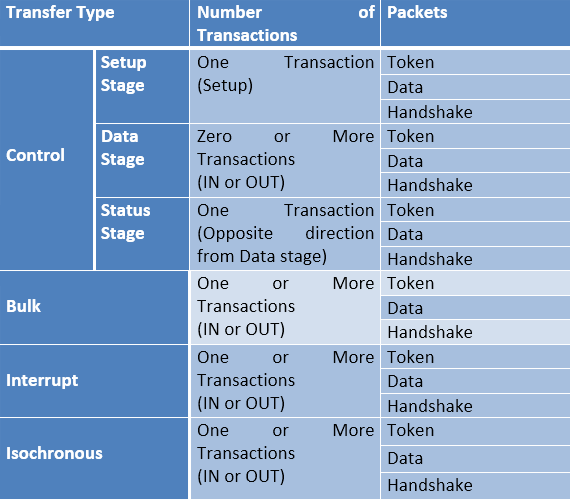
Fig. 10: Table Comparing Types of USB Transfers

Table Listing Transactions of Different USB Transfers


Fig. 11: Table Listing Transactions of Different USB Transfers

The upcoming article in the series talks about the various types of USB descriptors

You may also like:


  • What is LoRa and LoRaWAN?

  • What are LoRa gateways and what types are available?

  • What is the LoRaWAN network and how does it work?

  • What is Lightweight Internet Protocol (LwIP)?

  • What are different types of IoT networks?

  • What is an SoC?

Filed Under: Tutorials, USB


Next Article

← Previous Article
Next Article →

Questions related to this article?
👉Ask and discuss on EDAboard.com and Electro-Tech-Online.com forums.


Tell Us What You Think!! Cancel reply

You must be logged in to post a comment.

EE TECH TOOLBOX

“ee
Tech Toolbox: Internet of Things
Explore practical strategies for minimizing attack surfaces, managing memory efficiently, and securing firmware. Download now to ensure your IoT implementations remain secure, efficient, and future-ready.

EE Learning Center

EE Learning Center
“engineers
EXPAND YOUR KNOWLEDGE AND STAY CONNECTED
Get the latest info on technologies, tools and strategies for EE professionals.

HAVE A QUESTION?

Have a technical question about an article or other engineering questions? Check out our engineering forums EDABoard.com and Electro-Tech-Online.com where you can get those questions asked and answered by your peers!


RSS EDABOARD.com Discussions

  • Battery sensing circuitry for coin cell application
  • I/O constraint for Hold check
  • Question LCD LED IPS display
  • How can I get the frequency please help!
  • Fuel Gauge IC for Primary Cell Monitoring

RSS Electro-Tech-Online.com Discussions

  • how to work on pcbs that are thick
  • 100uF bypass Caps?
  • Fuel Auto Shutoff
  • Actin group needed for effective PCB software tutorials
  • compatible eth ports for laptop

Featured – Designing of Audio Amplifiers part 9 series

  • Basics of Audio Amplifier – 1/9
  • Designing 250 Milli Watt Audio Power Amplifier – 2/9
  • Designing 1 Watt Audio Power Amplifier – 3/9
  • Designing a Bass Boost Amplifier – 4/9
  • Designing a 6 Watt Car Audio Amplifier – 5/9
  • Design a low power amplifier for headphones- 6/9

Recent Articles

  • ITG Electronics releases gate drive transformers with 200 – 450 V DC capability
  • Stackpole introduces HCJ jumpers with 70.7 amp continuous current capability
  • Infineon releases MCU with 128K flash and multi-sense capabilities
  • ST introduces 600V GaN gate drivers with 300 ns start-up time
  • ABLIC releases S-19116 automotive voltage detector with 6.8μs response time

EE ENGINEERING TRAINING DAYS

engineering

Submit a Guest Post

submit a guest post
Engineers Garage
  • Analog IC TIps
  • Connector Tips
  • Battery Power Tips
  • DesignFast
  • EDABoard Forums
  • EE World Online
  • Electro-Tech-Online Forums
  • EV Engineering
  • Microcontroller Tips
  • Power Electronic Tips
  • Sensor Tips
  • Test and Measurement Tips
  • 5G Technology World
  • Subscribe to our newsletter
  • About Us
  • Contact Us
  • Advertise

Copyright © 2025 WTWH Media LLC. All Rights Reserved. The material on this site may not be reproduced, distributed, transmitted, cached or otherwise used, except with the prior written permission of WTWH Media
Privacy Policy

Search Engineers Garage

  • Electronics Projects and Tutorials
    • Electronic Projects
      • Arduino Projects
      • AVR
      • Raspberry pi
      • ESP8266
      • BeagleBone
      • 8051 Microcontroller
      • ARM
      • PIC Microcontroller
      • STM32
    • Tutorials
      • Audio Electronics
      • Battery Management
      • Brainwave
      • Electric Vehicles
      • EMI/EMC/RFI
      • Hardware Filters
      • IoT tutorials
      • Power Tutorials
      • Python
      • Sensors
      • USB
      • VHDL
    • Circuit Design
    • Project Videos
    • Components
  • Articles
    • Tech Articles
    • Insight
    • Invention Stories
    • How to
    • What Is
  • News
    • Electronic Product News
    • Business News
    • Company/Start-up News
    • DIY Reviews
    • Guest Post
  • Forums
    • EDABoard.com
    • Electro-Tech-Online
    • EG Forum Archive
  • DigiKey Store
    • Cables, Wires
    • Connectors, Interconnect
    • Discrete
    • Electromechanical
    • Embedded Computers
    • Enclosures, Hardware, Office
    • Integrated Circuits (ICs)
    • Isolators
    • LED/Optoelectronics
    • Passive
    • Power, Circuit Protection
    • Programmers
    • RF, Wireless
    • Semiconductors
    • Sensors, Transducers
    • Test Products
    • Tools
  • Learn
    • eBooks/Tech Tips
    • Design Guides
    • Learning Center
    • Tech Toolboxes
    • Webinars & Digital Events
  • Resources
    • Digital Issues
    • EE Training Days
    • LEAP Awards
    • Podcasts
    • Webinars / Digital Events
    • White Papers
    • Engineering Diversity & Inclusion
    • DesignFast
  • Guest Post Guidelines
  • Advertise
  • Subscribe