Engineers Garage

  • Electronic Projects & Tutorials
    • Electronic Projects
      • Arduino Projects
      • AVR
      • Raspberry pi
      • ESP8266
      • BeagleBone
      • 8051 Microcontroller
      • ARM
      • PIC Microcontroller
      • STM32
    • Tutorials
      • Audio Electronics
      • Battery Management
      • Brainwave
      • Electric Vehicles
      • EMI/EMC/RFI
      • Hardware Filters
      • IoT tutorials
      • Power Tutorials
      • Python
      • Sensors
      • USB
      • VHDL
    • Circuit Design
    • Project Videos
    • Components
  • Articles
    • Tech Articles
    • Insight
    • Invention Stories
    • How to
    • What Is
  • News
    • Electronic Product News
    • Business News
    • Company/Start-up News
    • DIY Reviews
    • Guest Post
  • Forums
    • EDABoard.com
    • Electro-Tech-Online
    • EG Forum Archive
  • DigiKey Store
    • Cables, Wires
    • Connectors, Interconnect
    • Discrete
    • Electromechanical
    • Embedded Computers
    • Enclosures, Hardware, Office
    • Integrated Circuits (ICs)
    • Isolators
    • LED/Optoelectronics
    • Passive
    • Power, Circuit Protection
    • Programmers
    • RF, Wireless
    • Semiconductors
    • Sensors, Transducers
    • Test Products
    • Tools
  • Learn
    • eBooks/Tech Tips
    • Design Guides
    • Learning Center
    • Tech Toolboxes
    • Webinars & Digital Events
  • Resources
    • Digital Issues
    • EE Training Days
    • LEAP Awards
    • Podcasts
    • Webinars / Digital Events
    • White Papers
    • Engineering Diversity & Inclusion
    • DesignFast
  • Guest Post Guidelines
  • Advertise
  • Subscribe

Voltage Doubler Circuit Using IC 4049

By Ashutosh Bhatt November 16, 2012

The circuit described here would produce an output voltage having twice the magnitude of the input voltage. In this circuit, we are using 6 Volts as input supply and we are getting 12 volts as its output. It is based on the popularly used hex inverter CD4049 IC. This can be made with the help of single IC with few more components.
CD4049 contains six inverter gates in one package as shown in diagram. In this, pin 3 is input and 2 is for output. For first gate similarly pin 5 is input and pin 4 is output for second gate similarly we have four more gates. Pin1 1 is for supply voltage and pin 8 is connected to ground. Pin 13 and 16 are unused.

[[wysiwyg_imageupload:6731:]]

Fig. 1: Pin Diagram Of CD4049 IC with Six Inverter Gates


The voltage doubler circuit is based on NOT gate CD4049 IC. We are utilizing all 6 gates of NOT gate. To understand the working you should know about the truth table of NOT gate are as follows-

Input
Output
0
1
1
0


In NOT gate, we will get output as logic high when logic zero is provided and we will get logic zero when logic1 is provided in input.

CD4049 contain six inverter gates in one package as shown in diagram. In this pin 3 is in and 2 is for output for  first gate similarly pin 5 is input and pin 4 is output for second gate similarly we have four more gate. In this 1 is for supply voltage and pin is connected to ground and pin 13 and 16 are unused pin.
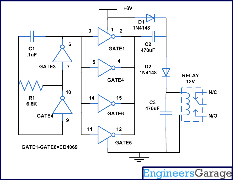
In this circuit we are utilizing all six gates of NOT gate. Firstly we have made an oscillator with the help of gate 3 and 4, capacitor C1 and resistor  R1. The frequency of oscillation is determined by the value of R1 and C1. The remaining gates are joined in parallel to act as a buffer. Input pins 3, 5, 14 and 11 are connected together and join to the frequency source from oscillator. Similarly we have connected all output pin 2,4,15 and 12 and terminated to voltage enhancer circuit.
A voltage multiplier circuit can be made with the help of a diode and a capacitor. This can be used to generate more output voltage than the supplied input. Here we are using most popular commonly used half wave series multiplier.
The requirement to make a voltage doubler circuit is 2 diodes, 2 capacitors and an oscillating voltage. As you can see from the circuit in this diode D1 is forward bias and conducts which in turns chare the capacitor C2 to the peak value of input voltage which now turns as a battery in series with the power supply. At the same time D2 conducts because of D1 and charges capacitor C3.Therefore voltage across C3 will be sum of supply voltage and voltage across C2. The main advantage of this voltage doubler circuit is that it allows higher voltage to be created from a low source without the need of a transformer.
Hence at the output of Diode D2 you can operate 12V relay with the help of 6volts supply. 
Also check the Voltage Doubler Circuit using 555 Timer IC

Circuit Diagrams

Circuit-Diagram-For-Voltage-Doubler-Circuit-Using-IC-4049

Project Components

  • Capacitor
  • Diode 1N4148
  • Relay Switch
  • Resistor


Filed Under: Electronic Projects
Tagged With: 4049, ic, voltage, voltage doubler
 

Next Article

← Previous Article
Next Article →

Questions related to this article?
👉Ask and discuss on EDAboard.com and Electro-Tech-Online.com forums.


Tell Us What You Think!! Cancel reply

You must be logged in to post a comment.

EE TECH TOOLBOX

“ee
Tech Toolbox: 5G Technology
This Tech Toolbox covers the basics of 5G technology plus a story about how engineers designed and built a prototype DSL router mostly from old cellphone parts. Download this first 5G/wired/wireless communications Tech Toolbox to learn more!

EE Learning Center

EE Learning Center
“engineers
EXPAND YOUR KNOWLEDGE AND STAY CONNECTED
Get the latest info on technologies, tools and strategies for EE professionals.

HAVE A QUESTION?

Have a technical question about an article or other engineering questions? Check out our engineering forums EDABoard.com and Electro-Tech-Online.com where you can get those questions asked and answered by your peers!


RSS EDABOARD.com Discussions

  • Diode recovery test Irrm timing.
  • How to make string LEDs?
  • The Analog Gods Hate Me
  • Battery Deep Discharge – IC Workarounds?
  • Safe Current and Power Density Limits in PCB Copper(in A/m² and W/mÂł) simulation

RSS Electro-Tech-Online.com Discussions

  • Raise your hand if your car had one of these:
  • Tektronix 2235 channel 1 trace unstable
  • How to make string LEDs?
  • Wideband matching an electrically short bowtie antenna; 50 ohm, 434 MHz
  • The Analog Gods Hate Me

Featured – LoRa/LoRaWan Series

  • What is the LoRaWAN network and how does it work?
  • Understanding LoRa architecture: nodes, gateways, and servers
  • Revolutionizing RF: LoRa applications and advantages
  • How to build a LoRa gateway using Raspberry Pi
  • How LoRa enables long-range communication
  • How communication works between two LoRa end-node devices

Recent Articles

  • Tria modules integrate edge AI processing with multi-core processors
  • pSemi introduces RF switch with 52 dBm PMAX,PEAK and 90-dBm IIP3 linearity
  • XP Power launches 1.3 kW power supply with 58.9 W/cmÂł density
  • How to enable Wi-Fi provisioning in ESP32-based IoT products
  • Amphenol RF introduces FAKRA to SMA adapters with 4 GHz operating frequency

EE ENGINEERING TRAINING DAYS

engineering

Submit a Guest Post

submit a guest post
Engineers Garage
  • Analog IC TIps
  • Connector Tips
  • Battery Power Tips
  • DesignFast
  • EDABoard Forums
  • EE World Online
  • Electro-Tech-Online Forums
  • EV Engineering
  • Microcontroller Tips
  • Power Electronic Tips
  • Sensor Tips
  • Test and Measurement Tips
  • 5G Technology World
  • Subscribe to our newsletter
  • About Us
  • Contact Us
  • Advertise

Copyright © 2025 WTWH Media LLC. All Rights Reserved. The material on this site may not be reproduced, distributed, transmitted, cached or otherwise used, except with the prior written permission of WTWH Media
Privacy Policy

Search Engineers Garage

  • Electronic Projects & Tutorials
    • Electronic Projects
      • Arduino Projects
      • AVR
      • Raspberry pi
      • ESP8266
      • BeagleBone
      • 8051 Microcontroller
      • ARM
      • PIC Microcontroller
      • STM32
    • Tutorials
      • Audio Electronics
      • Battery Management
      • Brainwave
      • Electric Vehicles
      • EMI/EMC/RFI
      • Hardware Filters
      • IoT tutorials
      • Power Tutorials
      • Python
      • Sensors
      • USB
      • VHDL
    • Circuit Design
    • Project Videos
    • Components
  • Articles
    • Tech Articles
    • Insight
    • Invention Stories
    • How to
    • What Is
  • News
    • Electronic Product News
    • Business News
    • Company/Start-up News
    • DIY Reviews
    • Guest Post
  • Forums
    • EDABoard.com
    • Electro-Tech-Online
    • EG Forum Archive
  • DigiKey Store
    • Cables, Wires
    • Connectors, Interconnect
    • Discrete
    • Electromechanical
    • Embedded Computers
    • Enclosures, Hardware, Office
    • Integrated Circuits (ICs)
    • Isolators
    • LED/Optoelectronics
    • Passive
    • Power, Circuit Protection
    • Programmers
    • RF, Wireless
    • Semiconductors
    • Sensors, Transducers
    • Test Products
    • Tools
  • Learn
    • eBooks/Tech Tips
    • Design Guides
    • Learning Center
    • Tech Toolboxes
    • Webinars & Digital Events
  • Resources
    • Digital Issues
    • EE Training Days
    • LEAP Awards
    • Podcasts
    • Webinars / Digital Events
    • White Papers
    • Engineering Diversity & Inclusion
    • DesignFast
  • Guest Post Guidelines
  • Advertise
  • Subscribe