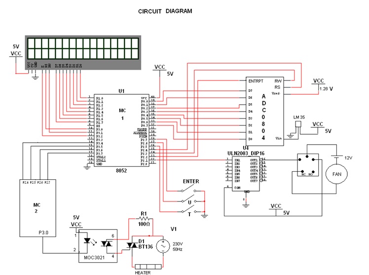
This project aims at developing an automated water temperature control system. This eliminates the human attention of controlling heater and fan. In this project, LM35 will sense the temperature of water in the container and will give output to the ADC in pin Vin. ADC will convert output of LM35 in to binary form. Then it is given to the microcontroller through port 0.Microcontroller will display the measured value from the LCD. Now controller will compare the measured value & the set point. Depending on error controller will generate the pwm to control the current flowing through the heater. PWM output signal trigger the opt isolator MOC3021 at specific time and that trigger Triac BT136. Now, when triac got triggered it allows flow of current through heater for specific period of time. Hence flow of current through heater controlled. If the error (set point – measured temperature) is negative, controller will start the fan through uln2003 and relay.

Fig. 1: Block Diagram of 8051 Microcontroller based Water Bath Temperature Controller
Apparatus:-


Project Source Code
###
For microcontroller 1: #include <REGX51.H>#define err_max 14
#define err_min 1sbit rs =P3^0;
sbit rw =P3^1;
sbit en =P3^2;sbit wr = P2^2;
sbit intr = P2^3;
sbit rd = P2^4;signed int count=0,f_count=0;
unsigned int timer=0,pwm,pwm1s;
unsigned char i,fmsc=0,dumy=0;
unsigned int buff,r,r1,s,s1,t1,t,loop,l,test=0,md[5]={0,0,0,0,0},rd1[5]={0,0,0,0,0};
signed int err=0,perr=0;
unsigned char sp_temp=20,u_sp=0,t_sp=2,mv=0;code unsigned char dig[10]="0123456789";
code unsigned char line1[16]=" Enter st point ";
code unsigned char line2[16]="SET PNT MV ";void lcdcmd(unsigned char value);
void lcddata(unsigned char value);
void msdelay(unsigned int k);
void display();
//void t_on();
//void t_off();void main()
{
P0=0xff;
TMOD=0x01;
IE=0x82;
TF0=0;
lcdcmd(0x38);
msdelay(30);
lcdcmd(0x0C);
msdelay(30);
lcdcmd(0x01);
msdelay(30);
lcdcmd(0x06);
msdelay(30);
lcdcmd(0x80);
msdelay(30);// Setting the Set Point
lcdcmd(0x08);
msdelay(5);for(i=0;i<16;i++)
{
lcddata(line1[i]);
msdelay(50);
}
lcdcmd(0x0c);
msdelay(5);
while(dumy==0)
{
if(P2_5==0) // changed
{
dumy++;
}
if(P2_6==0) // changed
{
//while(u_sp==0);
u_sp+=1;
if(u_sp>9)
u_sp=0;
}if(P2_7==0) // changed
{
//while(t_sp==0);
t_sp+=1;
if(t_sp>8)
t_sp=2;
if(t_sp==8)
u_sp=0;
}sp_temp=(10*t_sp)+u_sp;
rd1[1]=sp_temp/10;
rd1[0]=sp_temp%10;lcdcmd(0xC0);
msdelay(50);
for(loop=0;loop<2;loop++)
{
l=1-loop;
lcddata(dig[rd1[l]]);
msdelay(60);
}}
lcdcmd(0x01);
msdelay(60);// measuring temp and PID
lcdcmd(0x08);
msdelay(5);// Infinte loop
while(1)
{
// ADC startrd=1;
wr=1;
msdelay(1);
wr=0;
msdelay(1);
wr=1;
while(intr==0)
{
display();
}
// data converted to digital form
rd=0;
msdelay(1);
mv=P0;// data stored into mv
//PID algo..err=sp_temp-mv;
if(err>err_max)
err=err_max;
if(err<err_min)
err=err_min;pwm=err;
//pwm1 = pwm & 0x0f;
P3 = pwm & 0x0f;//count=pwm-7;
if(err==err_min)
{P2_1=0;}
else
{P2_1=1;}// t_on();
// t_off();display();
lcdcmd(0x0c);
msdelay(30);
}
}void display()
{
// Line 1 displaylcdcmd(0x80);
msdelay(30);for(i=0;i<16;i++)
{
lcddata(line2[i]);
msdelay(30);
}
// Line 2 SET PNT displayrd1[1]=sp_temp/10;
rd1[0]=sp_temp%10;lcdcmd(0xC0);
msdelay(50);for(loop=0;loop<2;loop++)
{
l=1-loop;
lcddata(dig[rd1[l]]);
msdelay(60);
}
// Line 2 MV display
md[1]=mv/10;
md[0]=mv%10;lcdcmd(0xCC);
msdelay(50);
for(loop=0;loop<2;loop++)
{
l=1-loop;
lcddata(dig[md[l]]);
msdelay(30);
}
}void lcdcmd(unsigned char value)
{
P1=value;
rs=0;
rw=0;
en=1;
msdelay(30);
en=0;
}void lcddata(unsigned char value)
{
P1=value;
rs=1;
rw=0;
en=1;
msdelay(30);
en=0;
}void msdelay(unsigned int k)
{
unsigned int i,j;
for(i=0;i<k;i++)
{
for(j=0;j<100;j++)
{;}
}
}//void t_on()
//{
//
// P2_0=0;
// TH0=0xDB;
// TL0=0xff;
// timer=(TH0*256)+(TL0);
// timer=timer-(count*1290);
// TH0=timer/256;
// TL0=timer%256;
//
// TR0=1;
// while(TF0==0);
// TR0=0;
// TF0=0;
//
//}
//
//void t_off()
//{
// P2_0=1;
// TH0=0xdb;
// TL0=0xff;
// timer=(TH0*256)+(TL0);
// timer=timer+(count*1290);
// TH0=timer/256;
// TL0=timer%256;
// TR0=1;
// while(TF0==0);
// TR0=0;
// TF0=0;
//}
For microcontroller-2:#include <REGX52.H>
void t_on();
void t_off();
signed int count=-7;
unsigned int timer=0;
unsigned char scan=0;void main()
{
TMOD=0x01;
IE=0x82;
TF0=0;while(1)
{
scan=P2;
count = scan -7;
if (count < -7)
count =-7 ;
if(count >7 )
count =7 ;
}
t_on();
t_off();
P1=scan;
}void t_on()
{
P3_0=0;
TH0=0xDB;
TL0=0xff;
timer=(TH0*256)+(TL0);
timer=timer-(count*1290);
TH0=timer/256;
TL0=timer%256;TR0=1;
while(TF0==0);
TR0=0;
TF0=0;}
void t_off()
{
P3_0=1;
TH0=0xdb;
TL0=0xff;
timer=(TH0*256)+(TL0);
timer=timer+(count*1290);
TH0=timer/256;
TL0=timer%256;
TR0=1;
while(TF0==0);
TR0=0;
TF0=0;
}
###
Circuit Diagrams
Filed Under: Electronic Projects

Questions related to this article?
👉Ask and discuss on EDAboard.com and Electro-Tech-Online.com forums.
Tell Us What You Think!!
You must be logged in to post a comment.