The project uses a sensor circuit to detect the water level of tank and transmits the level indication on an RF Module to the AC Motor control circuit. The motor control circuit displays the current water level and operates a relay to start or stop AC motor according to the water level of the tank. Most of such water level indication systems right now available in markets (available as Home Automation Systems) are wired and are costlier to install in a building of multiple storeys or buildings having greater areas. The benefit of using wireless system to interconnect water level detector and motor control circuit is that the cost to install the system is reduced and such system can be easily installed in multi-storey buildings and large building complexes.
The RF module used to bridge the indicator and motor control circuit is 434 MHz RF module. It has typical operational range of 50-60 metre (still enough for 10-15 storey apartments). Its range can be increased to 300 to 350 metre by using antenna and increasing the transmission power of the RF Module. This way RF module make the water level indicator system really advanced and better accessible. Also, there needs not to engage into complexity of wiring with great cost-cutting advantage.

Fig. 1: Prototype of Arduino based Wireless Water Level Indicator
Components Required
| Sr. No. | Components Required | Quantity |
|---|---|---|
| 1 | RF Tx module(434Mhz) | 1 |
| 2 | RF Rx module(434Mhz) | 1 |
| 3 | HT12E | 1 |
| 4 | HT12D | 1 |
| 5 | LED | 1 |
| 6 | Resistor – 1KΩ (Quarter watt) | 4 |
| 7 | Resistor – 1MΩ (Quarter watt) | 1 |
| 8 | Resistor – 50KΩ (Quarter watt) | 1 |
| 9 | Arduino pro mini development board | 1 |
| 10 | 16X2 LCD | 1 |
| 11 | BC547 Transistor | 1 |
| 12 | 1 C/O Type PCB mount relay | 1 |
| 13 | 1N4007 DIODE | 1 |
| 14 | 100 Ω (Quarter watt) resistor | 1 |
| 15 | 10k Pot | 1 |
| 16 | Battery – 9V | 2 |
| 17 | Breadboard | 3 |
| 18 | Connecting wires |

Fig. 2: Block Diagram of Arduino based Wireless Water Level Indicator
Circuit Connections
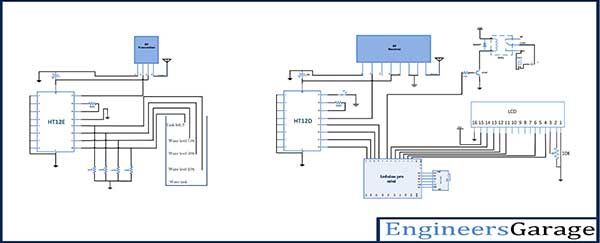
The Project has two circuit sections. One is the water level detection circuit and other is the motor control circuit. The water level detection circuit is more or less just an RF transmitter with bare wires connecting to its data pins. The principle here used for water detection is the conductivity of water. The fresh water is usually not a good conductor of electricity but the drinking water supplied in the households has minerals and salts dissolved in it in a controlled proportion. The presence of salts and minerals in the drinking water makes it a good conductor of electricity. For water level detection in a tank, a wire connected to VCC is laid down at the bottom of the tank. The wires having naked exposure for detecting the water level are laid at different heights inside the tank. Like if the tank is 8 metre deep or high, a wire corresponding to 25% filling is placed to a depth of 2 metre above the bottom of the tank. Similarly, wires corresponding to 50%, 75% and 100% are also laid according to the depth or height of the water tank. These wires are connected at the data pins of HT12E encoder IC of the RF module. The HT12E encoder has circuit configuration as dictated by its datasheet. Learn about the basic setup of RF module. The address pins of the encoder are hard wired to ground to assign it an address byte of 0x00 and pin 14 is also connected to ground to enable uninterrupted transmission. The RF transmitter’s data input connects to pin 17 of the decoder and has an antenna of 17.25 cm height connected at its pin 4. A series of pull-up resistors is connected at the data pins of encoder IC to drop the required voltage at the pins.
On the motor control circuit, RF transmitter is used which has an antenna connected at pin 8 and serial data out from pin 2 connected to pin 14 of the HT12D decoder IC. The decoder IC also has all the address bits fixed connected to ground to match the 0x00 address byte of the transmitter. The data pins D0 to D3 of the decoder IC parallel out the 4-bit data to pins 13 down to 10 of the Arduino Pro Mini. An LCD is interfaced to the Arduino board with data pins of the LCD connected to pin 7 to 4 of the Arduino and RS and E connected to pins 3 and 2 of Arduino respectively. A relay is connected to pin 8 of the Arduino board which switches ON or OFF the AC motor. In the project a bulb has been connected to the relay to show ON/OFF operation of the AC motor.

Fig. 3: Image showing RF circuit designed on a breadboard
How the Circuit Works
The working of this project is based on three main implementations – a) Detection of water level of the tank, b) RF transmission of level indicator and c) Execution of motor control by Arduino along with flashing current water level to LCD. The water level indication works on the principle of conductivity of electricity by the drinking water. The drinking water is a good conductor of electricity due to presence of salts and minerals. When the water level rises, it touches the naked wires laid for water level detection. This allows flow of current from the bottom laid wire connected to VCC to the naked wire the water has touched due to conductivity of electricity through water. When current flows through the level indicator wire, a voltage is dropped at the pull-up resistor connected between the junction of level indicator wire and data pin and the ground. This voltage drop causes a HIGH logic at the data pin. This is the reason that pull-up resistors are used at the data pins. So like, water reaches 25%, then data pin D3 gets a HIGH logic. The lower level indicator wires are connected to higher data bit denomination pin. This is because when water level rises, a HIGH logic is received at all the pins that have been interfaced to level indicator wires up to that level. So if water has raised to 75%, not only a HIGH logic will be received at respective D1 pin but also D2 and D3 as well. The program code checks the level indication from lower to higher denomination bit that is why lower level indicator wires are connected to higher data bit denomination pin.
With receiving HIGH logic at data pins of the encoder IC, a new signal nibble is transmitted over the RF system. The data is received by the RF receiver and serially passed to the HT12D decoder IC. The same data is latched at the data pins of the decoder. The data pins of decoder are connected to pin 13 down to 10 of Arduino board which are set to the digital input in the program code. The embedded program checks out each data bit individually and flash out the respective water level to the interfaced LCD screen. Following is the mapping of data pins corresponding to water levels of the tank.
| Data bit | Water level of tank |
|---|---|
| D0 | 100 % |
| D1 | 75 % |
| D2 | 50 % |
| D3 | 25 % |
When the water level drops below 25%, all the bits have a status LOW and the program code passes a LOW signal to pin 8 connected to relay therefore starting the AC motor ON. When water level reaches 100%, only D0 is HIGH, Arduino latches out a HIGH logic to pin 8 where relay is connected therefore switching the AC motor OFF. The pin 8 is configured digital out in the program.
Programming Guide
The embedded program runs on the Arduino board. When the board is powered on, the program executes continuously in a loop. First the program code imports and loads the required standard libraries LiquidCrystal.h for LCD and Wire.h for configuring digital I/O pins. The pins connected to data pins of decoder IC are assigned “tx<number>” reference and are mapped to pins 13 down to 10 of the Arduino. The pin 8 connecting to relay is assigned to “relay” variable and pins connecting LCD are mapped to pins 2 up to 7 in an array “lcd”.
#include <LiquidCrystal.h>
#include <Wire.h>
//decoder 10,11,12,13 output pins connected to arduino 10,11,12,13 digital pins as input.
int tx1 = 10;
int tx2 = 11;
int tx3 = 12;
int tx4 = 13;
int relay = 8;
LiquidCrystal lcd(2, 3, 4, 5, 6, 7);
A setup() function is called, inside which, pins mapped to data pins of decoder are set to digital input while pin connecting to relay is set to digital output by using pinMode() function. The baud rate of the Arduino board is set to 9600 bits per second using Serial.begin() function and LCD is initialized using lcd.begin function on the “lcd” object. Initial messages are flashed to the LCD and a HIGH status is assigned to pin connecting relay.
A loop() function is called where pins mapped to data pins of decoder have their status read by digitalRead() function and status of each data pin is checked using an if-else-if logic.
If Tx1 variable corresponding to D0 bit and 100% water level is high along with all the lower water level indication bits, a message “Tank Full” is flashed on the LCD and a HIGH output is latched to relay connected pin to operate the AC motor OFF.
Otherwise, if Tx1 corresponding to 100% water level is LOW but Tx2 corresponding to 75% water level is HIGH along with all the lower water level indication bits, a message “Water Level 75%” is flashed on the LCD.
Otherwise, if Tx1 corresponding to 100% and Tx2 corresponding to 75% water level are LOW but Tx3 corresponding to 50% water level is HIGH along with Tx4 corresponding to 25% water level indication, a message “Water Level 50%” is flashed on the LCD.
Otherwise if only Tx4 corresponding to water level 25% is HIGH, a message “Water Level 25% ” is flashed on the LCD.
Finally, if all the water level indication bits are low, a message “Water Level Below 25%” is flashed out on LCD and a LOW is latched out to relay connecting pin to operate the AC motor ON.
Project Source Code
###
#include#include //decoder 10,11,12,13 output pins connected to arduino 10,11,12,13 digital pins as input. int tx1 = 10; int tx2 = 11; int tx3 = 12; int tx4 = 13; int relay = 8; LiquidCrystal lcd(2, 3, 4, 5, 6, 7); void setup(){ pinMode(tx1,INPUT); pinMode(tx2,INPUT); pinMode(tx3,INPUT); // decoder output microcontroller reading as input. pinMode(tx4,INPUT); pinMode(relay,OUTPUT); Serial.begin(9600); lcd.begin(16, 2); lcd.print("ENGINEERS GARAGE"); lcd.setCursor(0, 1); digitalWrite(relay,HIGH); delay(1000); } void loop(){ // reading data and storing in a variable for further use. int Tx1 = digitalRead(tx1); int Tx2 = digitalRead(tx2); int Tx3 = digitalRead(tx3); int Tx4 = digitalRead(tx4); if (Tx1 == HIGH && Tx2 == HIGH && Tx3 == HIGH && Tx4 == HIGH ) { lcd.setCursor(0, 2); lcd.print("Tank Full"); lcd.print(" !!!! "); // change the analog out value: digitalWrite(buzzer,HIGH); delay(1000); digitalWrite(relay,HIGH); else if (Tx1 == LOW && Tx2 == HIGH && Tx3 == HIGH && Tx4 == HIGH ) { lcd.setCursor(0, 2); lcd.print("Water Level"); lcd.print(" 75%"); // change the analog out value: } else if (Tx1 == LOW && Tx2 == LOW && Tx3 == HIGH && Tx4 == HIGH ) { lcd.setCursor(0, 2); lcd.print("Water Level"); lcd.print(" 50%"); // change the analog out value: } else if (Tx1 == LOW && Tx2 == LOW && Tx3 == LOW && Tx4 == HIGH ) { lcd.setCursor(0, 2); lcd.print("Water Level"); lcd.print(" 25%"); // change the analog out value: } if (Tx1 == LOW && Tx2 == LOW && Tx3 == LOW && Tx4 == LOW ) { lcd.setCursor(0, 2); lcd.print("Water Level Below 25%"); lcd.print(" !!!! "); // change the analog out value: digitalWrite(buzzer,HIGH); delay(1000); digitalWrite(relay,LOW); } } ###
Circuit Diagrams
Project Video
Filed Under: Featured Contributions
Filed Under: Featured Contributions

Questions related to this article?
👉Ask and discuss on EDAboard.com and Electro-Tech-Online.com forums.
Tell Us What You Think!!
You must be logged in to post a comment.