This is programmable FM remote control can be used for some specific applications. Phase Lock Loop (PLL) IC-567 is used in transmitter and receiver part as oscillator and filter respectively. It can operate/control any device / application from the distance of around 50 meter (this range can be increased up to 1-2 Km if good transmitter is used).
A Phase Lock Loop (PLL) IC 567 is utilized in both transmitters as well as receiver part. In the Tx part IC-567 is configured such that it work as variable frequency oscillator. It generates four different frequencies. Standard FM mike (cordless mike) is used as FM transmitter which is used to modulate these 4 frequencies. At receiving side FM radio (which works as FM demodulator) demodulates the signal. Four different IC-567 all are configured as PLL to pass four different frequencies generated by Tx. At last signal will be given to micro-controller to perform some specific task.
Note:- The typical design limits the number of channels to 4 only because the filters used at receiving end cannot differentiate more frequencies. However 4 channels are enough for some specific industrial application. Here I have developed a particular application called “Programmable digital stop watch with remote”.
4-Channel FM transmitter
4-Channel FM transmitter:-
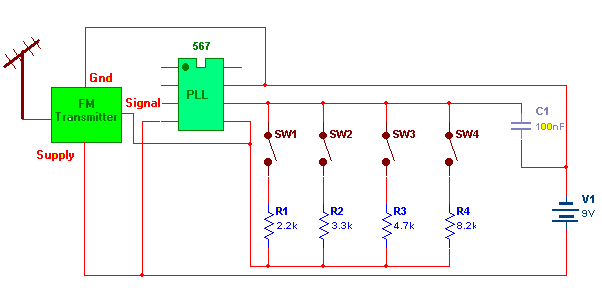
Circuit diagram tab 1 shows block diagram of 4-channel FM transmitter.
Connections:- It is a single chip circuit built around PLL IC567. The chip will work as oscillator if you connect resistor between pin no.-5 & 6 and a capacitor between pin 6 & 7. Output is taken from pin no.-5. and it is connected to input of FM Tx. Standard 9V battery supplies power to both chip and FM Tx.
Operation:- The frequency of oscillation is given by equation
Fosc = 1.1×R×C
So by pressing switch SW1-SW4 different resistor is selected (R1-R4) and so the generated frequency will also be changed. The output of chip is given to FM modulator so these four frequencies will be modulated over FM channel and transmitted.
4-channel FM receiver
4-channel FM receiver:-
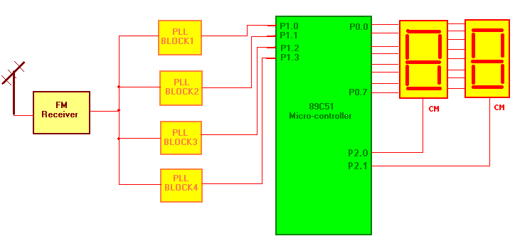
Circuit diagram tab 2 shows block diagram of micro-controller based FM receiver.
The main components are FM Radio Receiver, IC-567, 89C51 micro-controller and 7 segment LED display.
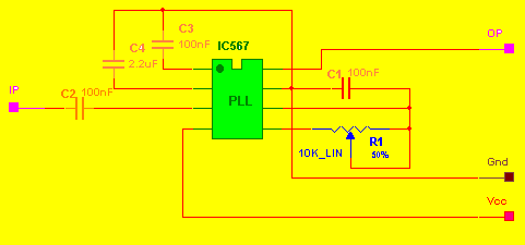
Connections:- The output of FM receiver is connected to all four inputs of PLL blocks (1 to 4). Internal circuit diagram of each PLL block is as shown in figure given below. The outputs of all four PLL blocks are given to port P1 of 89C51 chip. Port P0 drives two 7 segment LED displays. Two pins of port 2 (P2.0 & P2.1) are utilized to switch require display during operation.
Receiver Operation
Operation:- FM receiver will demodulate the signal and gives this signal to all four PLL blocks. As shown in figure all four IC567 are configured as phase lock loop means the output of chip (pin no.-8) will be low at one particular frequency determine by RC components connected to it. Again the freq. will be determine by equation
Fpll = 1.1×R×C
You can tune PLL to a particular frequency transmitted by Tx by varying 10K pot. Tune each PLL to a different frequency as transmitted by Tx so that it will produce low output every time whenever it receives that frequency. Please refer the table given below for more idea.
|
Switch |
Resistance |
PLL Block |
Pot adjustment* |
|
SW1 |
2.2K |
PLL Block No. 1 |
2.24K |
|
SW2 |
3.3K |
PLL Block No. 2 |
3.23K |
|
SW3 |
4.7K |
PLL Block No. 3 |
4.81K |
|
SW4 |
8.2K |
PLL Block No. 4 |
8.27K |
*Note:- pot adjustment may differ in every case
As you can see in figure the outputs of PLL blocks are given to 89C51 chip so rests will be handled by it. This particular application is developed as remote stop-watch. You can start, stop and change delay of stop watch from remote place. Four different switches performs four different tasks.
|
Sr. No. |
Switch |
Tasks |
|
1 |
SW1 |
Starts stop watch |
|
2 |
SW2 |
Stops stop watch |
|
3 |
SW3 |
Sets delay of 0.1 sec |
|
4 |
SW4 |
sets delay of 1 sec |
First you have to select time delay of 0.1 sec or 1 sec by pressing switch SW3-SW4. In both cases stop watch will count from 00-99 means in first case total time period will be 10 sec and in second it will be 100 sec. Then press SW1 and SW2 to start and stop the stop watch.
Project Source Code
Circuit Diagrams
Filed Under: Circuit Design

Questions related to this article?
👉Ask and discuss on Electro-Tech-Online.com and EDAboard.com forums.
Tell Us What You Think!!
You must be logged in to post a comment.