How to deal with any unknown stepper motor?
This section deals with a special procedure that can be useful to find out the type of stepper motor, its terminals, its coil sequence, its step resolution and everything about stepper motor. if anyone have a steppe motor that doesn’t have any specifications then after going through this section following the procedure he would be able to find out all above things for his stepper motor.
First, find out how many terminals or outcomes are provided for interface from stepper motor. If there are four terminals then it will be a bipolar stepper motor and if more than four means five of six terminals then it will be unipolar stepper motor. The construction of both motor is different and so the operation also.
Unipolar Stepper Motor: –
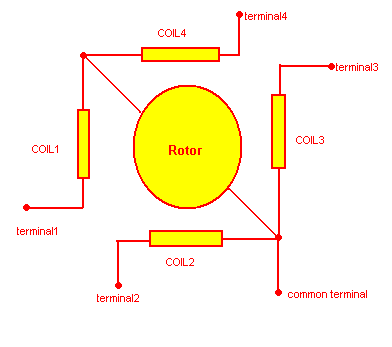
The given figure shows the internal architecture of unipolar stepper motor.
The stator has four coils and one end of each coil is tied to take out a common terminal. If the motor has six terminals then not all four but end of two coils are tied together and that two terminals are taken out as common.
Now to find out which terminal is common and which are for coil follow the procedure step by step
- take a multimeter and put it in continuity mode
- connect the red probe with any one terminal
- Now connect the black probe with any other terminal.
- if you are getting the coil resistance with each other terminals (any reading other then infinity) then the current terminal will be the common terminal
- And if you get the coil resistance with only one terminal then the second one will be common terminal. Check it with all other terminals.
- After identifying terminals, we have to find out the exact coil sequence how they are arranged because the motor will not rotate till the pulses applied in correct sequence.
- For this, you have to make one test circuit on general purpose PCB or breadboard and write a simple program in C language through u can find out coil sequence.
-
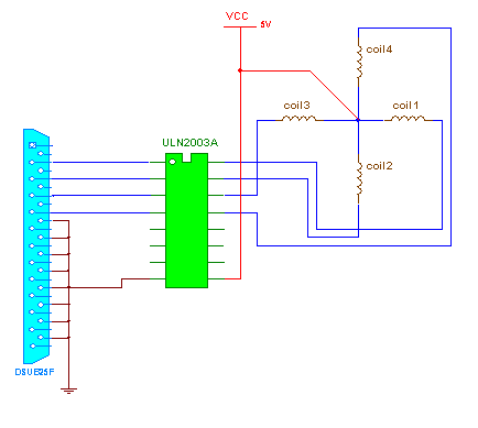
Unipolar Stepper Motor Circuit
- The circuit is as shown in Circuit Tab1. One and only component of circuit is current driver chip ULN2003A.
- connection:- all the inputs of chip (pin no.- 1, 2, 3, 4) are connected with the data pins (D0-D4) of 25 pin D type female connector (LPT connector). The outputs (pin no.- 16, 15, 14, 13) are connected with all four coil terminals. The common terminal is connected with +5 V. The chip is given bias on pin no. 9 and 8 as shown
- operation: – the chip consists of 8 Darlington pairs one for each input. When you apply high input from computer through LPT port, it will give low logic at output side so current can pass through the coil of motor.
- Now we have to write a program in C language that will give the pulses to LPT port and rotate the motor.
- There are three operating modes of unipolar stepper motor (1) single coil (2) double coil and (3) half step. From these three modes, we shall use first mode means only one coil will be energized at a time.
- as four coils are connected with four data outputs of LPT port D0-D3 the output data bytes will be 01h, 02h, 04h and 08h. Please refer the table.
|
coil4 D3 |
coil3 D2 |
coil2 D1 |
coil1 D0 |
data byte |
|
0 |
0 |
0 |
1 |
01 h |
|
0 |
0 |
1 |
0 |
02h |
|
0 |
1 |
0 |
0 |
04h |
|
1 |
0 |
0 |
0 |
08 h |
If the motor rotates then bingo!!!! You have connected the coil in right sequence. but if it doesn’t try to change the sequence in program like try 1428, 1482, 2148, 2184 etc. or you can change the connection of coil terminals and keeping sequence 1248 as it is. At one time, motor will rotate clockwise or anticlockwise. Note down the sequence and give the coil numbers according to it.
Now to find out step resolutions just go on increasing counter (i) given in program. Every time see when motor completes one full revolution. See the count. As we are applying 4 pulses in one loop total applied pulses will be counter × 4. And the step resolution will be 360/counter×4. Let’s take an example. If counter is 50 then total pulses will be 200 and step resolution will be 360/200 = 1.8. To increase or decrease speed just change given delay. If delay is increased speed will decrease and vice versa.
Bipolar stepper motor
Bipolar stepper motor: –
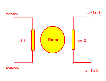
The given figure shows internal structure of bipolar stepper motor
Here there are only two coils in stator and its all four terminals are taken out no one is common. To rotate motor both coils must be energized in sequence and to energize coil one terminal of coil should be at high logic and second must be at low logic.
Here we just have to find out between which two terminals there are coil.
- take a multimeter and put it in continuity mode
- connect the red prob with any one terminal
- now connect the black probe with any other terminal.
- if you are getting the coil resistance (any reading other then infinity) then there must be one coil between these two terminal. If not then try other one
- once you get one coil terminals it is clear that other two will be for second coil.
- now to find out the sequence of terminals again we have to make a simple circuit and write a program in C language.
- there is only one operating mode so only one kind of pulse sequence is here. it is as shown in table
|
Coil 1 |
Coil 2 |
Data byte |
||
|
Terminal 1 |
Terminal 2 |
Terminal 3 |
Terminal 4 |
|
|
0 |
1 |
0 |
1 |
05 h |
|
1 |
0 |
0 |
1 |
09 h |
|
1 |
0 |
1 |
0 |
0A h |
|
0 |
1 |
1 |
0 |
06 h |
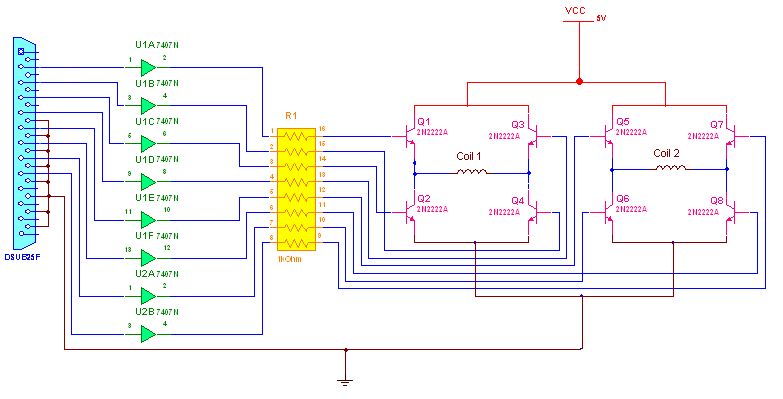
- to energize the coils in this manner we need a dual H-Bridge driver circuit as shown in Circuit Diagram Tab2
- it consist of 8 transistors, 8 resistors and 8 hex invertors.
- for more details about these circuit go through this link
- again we have to write a same program in C. everything all remains same then a data byte. The data bytes will be 33h, 3Ch, CCh and C3h.
if the motor doesn’t run, don’t change pulse sequence in program just change one of the coil terminal at a time not both. Try again. If it doesn’t work again change second coil terminals. You have maximum four possibilities. In one connection, the motor will run clockwise and just by reverting second coil terminal motor will run anticlockwise.
Now to find out step resolution do the same procedure. Just go on increasing counter (i) given in program. Every time see when motor completes one full revolution. See the count. As we are applying 4 pulses in one loop total applied pulses will be counter×4. And the step resolution will be 360/counter×4. Let’s take an example. If counter is 5 then total pulses will be 200 and step resolution will be 360/20 = 18. To increase or decrease speed just change given delay. If delay is increased, speed will decrease and vice versa.
So that is how one can find out the terminals and other unknown parameters of any stepper motor which has no specification.
Project Source Code
Project Source Code
###
Code for Unipolar stepper Motor
#include
#include
Void main()
{
For(int i=0;i<5;i++)
{
Sound(500);
Outport(0x0378, 0x01);
Delay(100);
Outport(0x0378, 0x02);
Delay(100);
Nosound();
Outport(0x0378, 0x04);
Delay(100);
Outport(0x0378, 0x08);
Delay(100);
}
}
Code for Bipolar Stepper Motor
#include
#include
Void main()
{
For(int i=0;i<5;i++)
{
Sound(500);
Outport(0x0378, 0x33);
Delay(100);
Outport(0x0378, 0x3C);
Delay(100);
Nosound();
Outport(0x0378, 0xCC);
Delay(100);
Outport(0x0378, 0xC3);
Delay(100);
}
###
Circuit Diagrams
Filed Under: Circuit Design

Questions related to this article?
👉Ask and discuss on Electro-Tech-Online.com and EDAboard.com forums.
Tell Us What You Think!!
You must be logged in to post a comment.