Engineers Garage

  • Electronics Projects and Tutorials
    • Electronic Projects
      • Arduino Projects
      • AVR
      • Raspberry pi
      • ESP8266
      • BeagleBone
      • 8051 Microcontroller
      • ARM
      • PIC Microcontroller
      • STM32
    • Tutorials
      • Audio Electronics
      • Battery Management
      • Brainwave
      • Electric Vehicles
      • EMI/EMC/RFI
      • Hardware Filters
      • IoT tutorials
      • Power Tutorials
      • Python
      • Sensors
      • USB
      • VHDL
    • Circuit Design
    • Project Videos
    • Components
  • Articles
    • Tech Articles
    • Insight
    • Invention Stories
    • How to
    • What Is
  • News
    • Electronic Product News
    • Business News
    • Company/Start-up News
    • DIY Reviews
    • Guest Post
  • Forums
    • EDABoard.com
    • Electro-Tech-Online
    • EG Forum Archive
  • DigiKey Store
    • Cables, Wires
    • Connectors, Interconnect
    • Discrete
    • Electromechanical
    • Embedded Computers
    • Enclosures, Hardware, Office
    • Integrated Circuits (ICs)
    • Isolators
    • LED/Optoelectronics
    • Passive
    • Power, Circuit Protection
    • Programmers
    • RF, Wireless
    • Semiconductors
    • Sensors, Transducers
    • Test Products
    • Tools
  • Learn
    • eBooks/Tech Tips
    • Design Guides
    • Learning Center
    • Tech Toolboxes
    • Webinars & Digital Events
  • Resources
    • Digital Issues
    • EE Training Days
    • LEAP Awards
    • Podcasts
    • Webinars / Digital Events
    • White Papers
    • Engineering Diversity & Inclusion
    • DesignFast
  • Guest Post Guidelines
  • Advertise
  • Subscribe

8 channel IR remote with SM5021B & SM5032C Chips

By Ashutosh Bhatt April 21, 2008

This is single chip remote because transmitter and receiver are made up of single chip SM5021B and SM5032C respectively. Both chips are perfectly design for IR remote system by “Samhop microelectronics corp.”. It is an 8 channel remote with 2 inbuilt on/off controls & 6 pulse outputs. Before starting the project first go through the datasheets of both ICs.

General Description:-


You can design 8-channel IR remote control using these chips. Encoder chip SM5021 will generate a specific code for each key pressed modulate it with 38 KHz carrier and transmit it. Carrier is generated by internal crystal oscillator. Modulated o/p can directly drive IR LED through transistor. On receiver side decoder chip SM5032 will detect the code compare it and if match found then it will give pulse o/p on its o/p pins. There are total 8 output pins for 8 different channels two of them gives toggle o/p for on/off control.

Transmitter:-

Circuit diagram tab 1 shows schematic diagram of transmitter circuit using chip SM5021B. Its 16 pin IC 8 pins are for 8 channels, 2 for power supply (Vcc (16) & Gnd (8)), 2 for crystal connections (X1(12) & X2(13)), 2 for custom code (C1 (1) & C2 (2)) and last 2 for output. One is for modulated output (o/p (15)) and other is for LED output (14).   

Tx: Connection and Operation

Connections: – All key inputs of chip from K1 to K8 are connected to ground through push buttons switches S1 to S8. A 455 KHz crystal is connected between pins X1 & X2. Custom code pins C1 and C2 are directly connected to ground to setup a custom code 00.  LED is directly connected to LED output pin. The modulated o/p pin drives two IR LEDs through transistor 2N2222A. 9V standard battery is connected to power supply pins.

Operation: –    Whenever you press any switch that key i/p of IC is grounded and so a particular code is generated and transmitted. Every code is of 13 bits. The format of code is as given below

                        1    1    0        C1    C2        D7    D6    D5    D4    D3    D2    D1    D0

                       Start bits     Custom code                  data bits

·         First three bits are called start bits and they are always 110

·         Next two bits are custom code set by user. You can set any of these combination 00,01,10 or 11 (I have set it 00 by connecting C1 & C2 to ground)

·         Last 8 bits are data bits. The combination of these bits is different for each key input. Please refer the table given below 

Start bits

Custom Code

D7

D6

D5

D4

D3

D2

D1

D0

Key input

1

1

0

C1

C2

0

0

0

0

0

0

0

1

K1

1

1

0

C1

C2

0

0

0

0

0

0

1

0

K2

1

1

0

C1

C2

0

0

0

0

0

1

0

0

K3

1

1

0

C1

C2

0

0

0

0

1

0

0

0

K4

1

1

0

C1

C2

0

0

0

1

0

0

0

0

K5

1

1

0

C1

C2

0

0

1

0

0

0

0

0

K6

1

1

0

C1

C2

0

1

0

0

0

0

1

1

K7

1

1

0

C1

C2

1

0

0

0

0

0

1

1

K8

     These 13 bit codes are transmitted serially through modulated output pin o/p (15). IR LED will generate IR light beam of 38 KHz. At the same time green LED connected at LED output pin (14) will blink and indicate the code is transmitted.

Receiver

      Receiver

         Circuit diagram tab 2 shows Receiver circuit using decoder IC SM5032C. It is 14 pin IC. 1 input pin (2), 1 oscillator pin (13), 2 for custom code (C1 (12) & C2 (13)), 2 for supply (Vcc (14), Gnd (1)) and rest 8 are 8 outputs. Out of these 8, 6 (CP1 to CP6) are pulse output and 2 (TP1 and TP2) are toggle output.

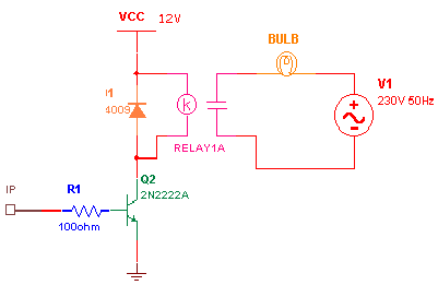
·         Connection: –   Output of IR sensor TSOP 1738 is connected to input of chip through transistor 2N2222A. Custom code pins C1 & C2 are directly connected to ground. Resistor R1 (43K?) and capacitor C1 (1nF) is connected to oscillator pin (13) as shown. LED is connected to each pulse output CP1 to CP6 and toggle outputs are connected to relay driving circuit. A typical relay firing circuit is as shown in figure below.

Output of IR sensor TSOP 1738

     Operation: –  IR sensor will detect 38 KHz IR light and recover the modulated code and give it to decoder chip. Decoder chip will compare start bits and custom code and if it matches then activates particular output depending upon the code received. Please refer the table.

Start bits

Custom Code

D7

D6

D5

D4

D3

D2

D1

D0

Output

1

1

0

C1

C2

0

0

0

0

0

0

0

1

CP1

1

1

0

C1

C2

0

0

0

0

0

0

1

0

CP2

1

1

0

C1

C2

0

0

0

0

0

1

0

0

CP3

1

1

0

C1

C2

0

0

0

0

1

0

0

0

CP4

1

1

0

C1

C2

0

0

0

1

0

0

0

0

CP5

1

1

0

C1

C2

0

0

1

0

0

0

0

0

CP6

1

1

0

C1

C2

0

1

0

0

0

0

1

1

TP1

1

1

0

C1

C2

1

0

0

0

0

0

1

1

TP2

     So whenever you press switch S1 from transmitter LED1 will blink and if you press S2 LED2 will blink and so on. When you press S7 or S8 the toggle output TP1 and TP2 will be activated. So when you first press S7 or S8 TP1/TP2 will be high again when you press S7/S8 TP1/TP2 will be low. Thus TP1 and TP2 will energize or de-energize the relay on alternate key press. So you can get ON/OFF control for any AC/DC device.                                                                      


Circuit Diagrams

Transmitter_0
Receiver


Filed Under: Electronic Projects
Tagged With: 8 channel, ir, remote, sm5021b, sm5032c
 

Next Article

← Previous Article
Next Article →

Questions related to this article?
👉Ask and discuss on EDAboard.com and Electro-Tech-Online.com forums.


Tell Us What You Think!! Cancel reply

You must be logged in to post a comment.

EE TECH TOOLBOX

“ee
Tech Toolbox: Internet of Things
Explore practical strategies for minimizing attack surfaces, managing memory efficiently, and securing firmware. Download now to ensure your IoT implementations remain secure, efficient, and future-ready.

EE Learning Center

EE Learning Center
“engineers
EXPAND YOUR KNOWLEDGE AND STAY CONNECTED
Get the latest info on technologies, tools and strategies for EE professionals.

HAVE A QUESTION?

Have a technical question about an article or other engineering questions? Check out our engineering forums EDABoard.com and Electro-Tech-Online.com where you can get those questions asked and answered by your peers!


RSS EDABOARD.com Discussions

  • How can I get the frequency please help!
  • Elektronik devre
  • 12VAC to 12VDC 5A on 250ft 12AWG
  • SPI speed pic18f66j15
  • Antiparallel Schottky Diodes VDI-Load Pull

RSS Electro-Tech-Online.com Discussions

  • Actin group needed for effective PCB software tutorials
  • how to work on pcbs that are thick
  • compatible eth ports for laptop
  • How to repair this plug in connector where wires came loose
  • Kawai KDP 80 Electronic Piano Dead

Featured – Designing of Audio Amplifiers part 9 series

  • Basics of Audio Amplifier – 1/9
  • Designing 250 Milli Watt Audio Power Amplifier – 2/9
  • Designing 1 Watt Audio Power Amplifier – 3/9
  • Designing a Bass Boost Amplifier – 4/9
  • Designing a 6 Watt Car Audio Amplifier – 5/9
  • Design a low power amplifier for headphones- 6/9

Recent Articles

  • ITG Electronics releases gate drive transformers with 200 – 450 V DC capability
  • Stackpole introduces HCJ jumpers with 70.7 amp continuous current capability
  • Infineon releases MCU with 128K flash and multi-sense capabilities
  • ST introduces 600V GaN gate drivers with 300 ns start-up time
  • ABLIC releases S-19116 automotive voltage detector with 6.8ÎĽs response time

EE ENGINEERING TRAINING DAYS

engineering

Submit a Guest Post

submit a guest post
Engineers Garage
  • Analog IC TIps
  • Connector Tips
  • Battery Power Tips
  • DesignFast
  • EDABoard Forums
  • EE World Online
  • Electro-Tech-Online Forums
  • EV Engineering
  • Microcontroller Tips
  • Power Electronic Tips
  • Sensor Tips
  • Test and Measurement Tips
  • 5G Technology World
  • Subscribe to our newsletter
  • About Us
  • Contact Us
  • Advertise

Copyright © 2025 WTWH Media LLC. All Rights Reserved. The material on this site may not be reproduced, distributed, transmitted, cached or otherwise used, except with the prior written permission of WTWH Media
Privacy Policy

Search Engineers Garage

  • Electronics Projects and Tutorials
    • Electronic Projects
      • Arduino Projects
      • AVR
      • Raspberry pi
      • ESP8266
      • BeagleBone
      • 8051 Microcontroller
      • ARM
      • PIC Microcontroller
      • STM32
    • Tutorials
      • Audio Electronics
      • Battery Management
      • Brainwave
      • Electric Vehicles
      • EMI/EMC/RFI
      • Hardware Filters
      • IoT tutorials
      • Power Tutorials
      • Python
      • Sensors
      • USB
      • VHDL
    • Circuit Design
    • Project Videos
    • Components
  • Articles
    • Tech Articles
    • Insight
    • Invention Stories
    • How to
    • What Is
  • News
    • Electronic Product News
    • Business News
    • Company/Start-up News
    • DIY Reviews
    • Guest Post
  • Forums
    • EDABoard.com
    • Electro-Tech-Online
    • EG Forum Archive
  • DigiKey Store
    • Cables, Wires
    • Connectors, Interconnect
    • Discrete
    • Electromechanical
    • Embedded Computers
    • Enclosures, Hardware, Office
    • Integrated Circuits (ICs)
    • Isolators
    • LED/Optoelectronics
    • Passive
    • Power, Circuit Protection
    • Programmers
    • RF, Wireless
    • Semiconductors
    • Sensors, Transducers
    • Test Products
    • Tools
  • Learn
    • eBooks/Tech Tips
    • Design Guides
    • Learning Center
    • Tech Toolboxes
    • Webinars & Digital Events
  • Resources
    • Digital Issues
    • EE Training Days
    • LEAP Awards
    • Podcasts
    • Webinars / Digital Events
    • White Papers
    • Engineering Diversity & Inclusion
    • DesignFast
  • Guest Post Guidelines
  • Advertise
  • Subscribe