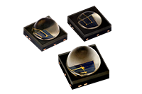
Vishay Intertechnology is broadening its optoelectronics portfolio with the release of six new 850 and 940 nm high-power infrared (IR) emitters that deliver best-in-class radiant intensity in 3.4 by 3.4 mm surface-mount packages. Built on Vishay’s SurfLight surface emitter chip technology, the Vishay Semiconductors devices are designed for high drive-currents up to 1.5 A DC…
DIY Circuit Diagram: Transmit and Receive Low Frequency Pulses using IR Modulator & Demodulator
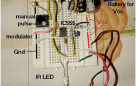
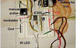
The circuit presented here is used to transmit and receive low frequency pulses using IR modulator and demodulator. IR modulator takes low frequency pulses as input. It modulates them on 38 KHz carrier and transmits them through IR LED as 38 KHz IR light. On the demodulator side IR sensor detects (receives) 38 KHz IR light. It demodulates this 38 KHz pulses and recovers transmitted low frequency pulses. One pulse generator is built using IC555 to generate low frequency pulses. IR modulator is also built using IC555 and TSOP1738 IR sensor is used as IR demodulator.
IR to RF Converter
Here we have presented a simple circuit using which you can convert IR signal into RF signals and at the same time transmit this to remote location and decode them using a compatible RF receiver. With help of this circuit you can increase the range of the device you are controlling up to 200 meters
How to Find Something Secretly using IR Radiation
To find something secretly you have to do something that has to be in a very secret manner. Never use this method to steal anything. If you will caught by this method than you can be jail for whole life time or you could be charged fine in few lakhs. There is only one way to do this. There is a light which cannot be seen by naked eye called IR light. This is not in the range of the visual range. Visual range is the range of light that can be seen by our naked eyes. By this advantage we can now make a machine that can find the item in the dark place. So let’s start this machine working. Infrared (IR) light is electromagnetic radiation with longer wavelengths than those of visible light, extending from the nominal red edge of the visible spectrum at 700 nanometers (nm) to 1 mm.
Remote Controlled Toy Car
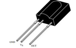
Remote control toy car circuit can be used to on and off the motor of the toy car with the help of your remote. You can use any remote of TV, AC, DVD player to control the movement of motors.This low cost circuit is based on the CD4017 counter IC which receives trigger pulse from IR sensor and switch ON the relay. And with the relay, motors are connected which also get switched ON. Upon receiving the second pulse motor gets turned OFF.You can control your toy car upto 5 meters range. This is a simple circuit based on infrared sensor IC TSOP1738. TSOP1738 contains photo detector and preamplifier in one package. It is three terminal device having pin 1 configured for ground, pin 2 for power supply and pin 3 as output. Keep on reading to find out how the circuit works.
Remote Tester Circuit
Today we are controlling many appliances with the help of remote like AC, TV or music system. It often happen that remote stops working due to any reason (lowbattery or any button of remote becomes faulty). Therefore circuit describes below help you to test your remote to identify that appliance (TV, AC etc) has problem or your remote is not responding. Advantage of circuit- Based on single sensor and hence circuit consumes very less power. Almost every remote can be tested with the help of this circuit as operating frequency of sensor is 38 KHz. High immunity against ambient light. With little modification in the circuit you can use it to control your home appliances with remote.
DC Gear motor rotation control
Here is very useful application that controls the number of rotation of 12 V DC gear motor with very low RPM (1,2,3,5 or 10 etc).You may find lots of [[wysiwyg_imageupload::]]applications of this project in robotics, CNC machines, manufacturing industries etc. Here are some of the examples In any PCB cutting or PVC pipe cutting CNC machine (or any other automatic cutting machine) first the linear dimensions are calibrated in terms of number of rotations (e.g. 5 rotations = 1 CM), then by adjusting the number of rotations as per required dimension one can easily move the cutting tool to that distance (e.g. for 1 meter 500 rotations). In robotic arm application, if the arm has to move to a specific position then first its movement can be calibrated in terms of number of rotations of motor. Afterwards once we program and set the number of rotations for a button, the arm will always move to that position when that button is pressed.
TSOP 1738: How to test TSOP1738
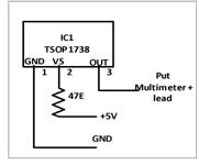
I am designing a circuit which can be controlled by TV or AC remote. For that I have purchase TSOP1738 with few more components from market. And I assemble my circuit carefully, then also I am not getting the desire output. I again rechecked my assembled circuit with the circuit diagram and I don’t find…
Insight: The internal working of a remote control
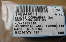
The Oxford Dictionary defines a remote control to be a “control of a machine or apparatus from a distance by means of radio or infrared signals transmitted from a device”. So, when we decided to go inside a conventional remote control, we were stuck: which one to take? There are those for LCD TV, others for gaming consoles, for the car entertainment systems and some that work for all kinds of systems. At the very first sight, one can notice difference in designs, features, the manner they are powered and several such features. But upon giving a slight thought, it is easy to understand that all the remotes are performing the same basic task: controlling outputs of an electric/electronic device. So, here we are, with a Sony RMGA020 LCD TV Remote used for their 32 inch KL television series. Interestingly, Sony calls their remote to be “Remote Commanders”. Since the trend nowadays is to equip remotes with a hoard of features and create the main gadget as simple as possible, calling them “Remote Commanders” is fair enough.
Tachometer using microcontroller
Here is a trial of building a tachometer using AT89S52 Microcontroller. This is a digital tachometer which works using infrared rays. The tachometer designed here can measure rotational speed up to 4200 rpm which is sufficient for small scale use. If the speed goes beyond 4200 rpm, it gives a message on the display screen as “OUT OF RANGE”.Take out the wheel of a damaged optical mouse and make a hole at the center of the wheel. Put the steel rod at the hole and glue it tightly so that the rod and the wheel rotate simultaneously. Make the plywood frame as shown in figure and screw the screw bearings on both sides so that the rod with the wheel can be mounted. After mounting the rod (with the wheel) on the screw bearings, try rotating the wheel with your finger. While rotating, the rod should have a minimum friction with the screw bearings.
Remote Control using IR codec chip ST12
Here to make a IR remote control I am using an ASIC codec chip ST12. Codec means coder+ decoder. That means same chip is used as encoder at transmitter side and as decoder at receiver side. It’s very nice chip and some of the major features of the chip are: Encode / Decode on single…
Multichannel IR Remote using 89C51
It’s multi channel IR remote control so you can perform not just single but so many functions with this remote control. Micro-controller 89C51 is used in receiver part so its programmable remote control. You can program it to perform specific task or for specific application. Some applications that I have developed are “Remote control for home appliances”,…
Passive Infrared Sensor (PIR Sensor)
When a communication is to be established, that too wirelessly, with a remote device, we typically employ optical radiations or radio waves or sometimes, acoustic waves (for underwater applications). These three types of wireless communications basically differ in their frequencies. All frequencies starting from frequency bands like LF, HF, VHF, UHF and so on, extending up to microwaves and millimeter waves are referred to as radio waves. Acoustic waves use ultrasonic portion of frequency spectrum. Optical Radiations use visible and infrared portion of the spectrum. Infrared sensors have been widely utilized for remote based applications such as in televisions etc. This article will detail with a Passive Infrared Sensor.
Wireless DC Motor Speed Control using IR and IC555
This is a very interesting application. We shall vary the speed of DC motor from a remote place without any wire connection. I am using PWM (pulse width modulation) method to very the speed of DC Motor. To make it wireless I am using IR transmitter and IR sensor. There are two sections in the circuit 1) PWM generator with IR modulator and 2) IR receiver and motor driver. Transmitter generates PWM wave of 50 Hz (20 ms) and modulates it over 38 KHz frequency. The IR sensor on receiver side will demodulate the PWM wave and drives the DC motor.
Wireless speed control of AC motor using IR and ZCD (Zero cross Detector)
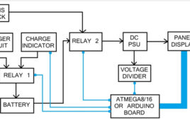
Here in this application, I will show you how we can control the speed of single phase 230V AC motor wirelessly using IC555. Along with IC555 I am using zero cross detector (ZCD) circuit to trigger the monostable and an optocoupler to trigger thyristor. Let us first see the block diagram of the AC Motor Speed Control System.
Remote Controlled Electrical Equipments
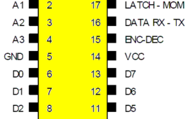
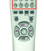
This device can be used to control (ON/OFF) eight high voltage electrical equipments with a remote control. The LEDs connected shows the status of the relays (ON or OFF). If one relay is ON then the corresponding LED will be ON otherwise it will be OFF. The remote control is shown in figure. The RED…
Controlling Audio Volume & Tone with a Remote Control
Here is the project of controlling audio volume and audio tone (bass and treble) with a remote control designed using microcontroller AT89S52.It is a mono audio controller and to make it stereo similar circuits have to be made for the both LEFT and RIGHT channels. I have not connected the components in a PCB…
Swarm Robotics
“When everybody thinks alike, nobody is thinking much”, is so rightly said. Think out-of-the-box and you potent some innovation or maybe an invention; credits to your gamut. To speak in line with the concept here, swarming population; not always, is a bad idea. How about rescuing some disaster hit zone with swarming intelligent population or maintaining a warehouse with moving, self-operational shelves?? A great idea indeed. Everybody must have noticed the movement of ants or similar insects. It is awesomely coordinated and aligned with respect to each other. They accomplish their task collectively by keeping an eye on each other’s movement. This type of coordinated movement in insects is termed as Swarm and when this movement is performed by some group of robots then in technical terms it is called as “Swarm Robotics” inspired by colonies of ants and swarms of bees.
Infrared Sensors or IR Sensors
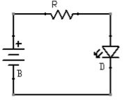
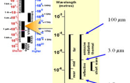
Infrared radiation is the portion of electromagnetic spectrum having wavelengths longer than visible light wavelengths, but smaller than microwaves, i.e., the region roughly from 0.75µm to 1000 µm is the infrared region. Infrared waves are invisible to human eyes. The wavelength region of 0.75µm to 3 µm is called near infrared, the region from 3 µm to 6 µm is called mid infrared and the region higher than 6 µm is called far infrared. Active infrared sensors employ both infrared source and infrared detectors. They operate by transmitting energy from either a light emitting diode (LED) or a laser diode. A LED is used for a non-imaging active IR detector, and a laser diode is used for an imaging active IR detector. In this types of IR sensors, the LED or laser diode illuminates the target, and the reflected energy is focused onto a detector. Photoelectric cells, Photodiode or phototransistors are generally used as detectors. The measured data is then processed using various signal-processing algorithms to extract the desired information.

