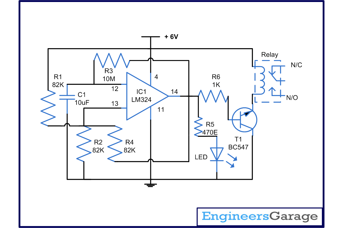
This timer circuit project is used to switch on and off the device for a fixed interval of time. In this case, it is taken to be 90 seconds, meaning that the device periodically becomes on for preset amount of time and remains off for same period of time. It can be set with the help of a resistor and a capacitor. LM324 is able to provide high gains and works in a power efficient mode, thus one can power it using a battery.
Using RC components for timing makes the calculations easier and also gives ability to alter the time period to a higher or a lower value.
In this timer circuit, pin 12 and 13 are input pin and pin 14 is output pin. Pin 4 is for supply while pin 11 is ground. When it comes to working, the circuit compares the voltage on pin 13 with respect to pin 12. When the power supply is applied, output voltage is low as pin 12 is low compared to pin 13. As a result, transistor connected to it does not work and relay remains off.
After some time, capacitor starts discharging and voltage at pin 12 become high in comparison to pin13. Pin 14 becomes high and the transistor starts conducting. This makes the device connected to relay start operating on and off for the time set, which is 90 seconds in this case.
Time period can be set by C1 and R3 when you increase the value time period will increase when you reduce the value time period will decrease.
Circuit Diagrams
Project Components
Filed Under: Electronic Projects


Questions related to this article?
👉Ask and discuss on EDAboard.com and Electro-Tech-Online.com forums.
Tell Us What You Think!!
You must be logged in to post a comment.