Engineers Garage

  • Electronic Projects & Tutorials
    • Electronic Projects
      • Arduino Projects
      • AVR
      • Raspberry pi
      • ESP8266
      • BeagleBone
      • 8051 Microcontroller
      • ARM
      • PIC Microcontroller
      • STM32
    • Tutorials
      • Sensor Series
      • Engineering Deep Dives
      • AI
      • ARDUINO Compatible Coding
      • Audio Electronics
      • Battery Management
      • Beginners Electronics Series
      • Brainwave
      • Digital electronics (DE)
      • Electric Vehicles
      • EMI/EMC/RFI
      • EVs
      • Hardware Filters
      • IoT tutorials
      • LoRa/LoRaWAN
      • Power Tutorials
      • Protocol
      • Python
      • RPI Python Programming
      • Sensors
      • USB
      • Thermal management
      • Verilog
      • VHDL
    • Circuit Design
    • Project Videos
    • Components
  • Articles
    • Tech Articles
    • Insight
    • Invention Stories
    • How to
    • What Is
  • News
    • Electronic Product News
    • Business News
    • Company/Start-up News
    • DIY Reviews
    • Guest Post
  • Forums
    • EDABoard.com
    • Electro-Tech-Online
    • EG Forum Archive
  • DigiKey Store
    • Cables, Wires
    • Connectors, Interconnect
    • Discrete
    • Electromechanical
    • Embedded Computers
    • Enclosures, Hardware, Office
    • Integrated Circuits (ICs)
    • Isolators
    • LED/Optoelectronics
    • Passive
    • Power, Circuit Protection
    • Programmers
    • RF, Wireless
    • Semiconductors
    • Sensors, Transducers
    • Test Products
    • Tools
  • Learn
    • eBooks/Tech Tips
    • Design Guides
    • Learning Center
    • Tech Toolboxes
    • Webinars & Digital Events
  • Resources
    • Digital Issues
    • EE Training Days
    • LEAP Awards
    • Podcasts
    • Webinars / Digital Events
    • White Papers
    • Engineering Diversity & Inclusion
  • Guest Post Guidelines
  • Advertise
  • Subscribe

Adjustable Timer Circuit

By Ashutosh Bhatt December 26, 2018


This multipurpose adjustable timer circuit will give you alarm after every specific interval of time. You can vary the time interval with the help of 8 way dip switch. Therefore this timer can be used in kitchen, or by students preparing for competitive exam. As many of us have habit to forget, to switch off button of gas, electric oven which lead to wastage of resources and your hard work. Now with the help of this circuit you will receive an alarm after specific time so that you can remember to off the device.Some other features of the circuit are: You can also use it as alarm to switch off the motor because while watching TV or talking over phone we forget to switch off the pump in that case also it will give an alarm. You can set the time period for coking also like we used to in microwave oven.


This multipurpose adjustable timer circuit will give you alarm after every specific interval of time. You can vary the time interval with the help of 8 way dip switch. Therefore this timer can be used in kitchen, or by students preparing for competitive exam.

As many of us have habit to forget, to switch off button of gas, electric oven which lead to wastage of resources and your hard work. Now with the help of this circuit you will receive an alarm after specific time so that you can remember to off the device. Some other features of the adjustable timer circuit are:

1. You can also use it as alarm to switch off the motor because while watching TV or talking over phone we forget to switch off the pump in that case also it will give an alarm. 

2. You can set the time period for coking also like we used to in microwave oven. 

3. Main advantage is this timer is it can be programmed for more than 250 different time interval. 

4. It works off a 9V PP3 battery and its stand by current is also very low. 


Description

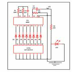
This simple circuit is based on CD4060 IC with few more components. IC CD4060 is 14 stage ripple carry binary counter, divider and an oscillator. Its built in oscillator is main feature of this IC. Hear IC1 is working as frequency dividing circuit. Its inbuilt oscillator is based on three inverters. The basic frequency of the internal oscillator is determined by the value of the capacitor connected to its pin 9 and the resistor connected to pin 10.

By increasing or decreasing the value of capacitor and resistor we can change the time delay for the period of on and off. Internally the oscillator signal is applied to the first bistable which drives the second bistable and so on. Since each bistable divides its input signal by two, a total of fifteen signals are available, each of half the frequency of the previous one. Output Qn is the nth stage of the counter, representing 2n, for example Q4 is 24 = 16 (1/16 of clock frequency) and Q14 is 214 = 16384 (1/16384 of clock frequency).

With the help of this circuit we can form more than 250 combination. This is possible with the help of diodes D1- D8 which are forming AND gate. As we know  AND gate will give us high output only when all inputs are high otherwise it will give you low output.

How AND gate is formed using diodes-

Diode is device which allow current to flow in one direction. Consider a case where anode terminal is at higher voltage in comparison to cathode than diode is said to in forward bias and its resistance is very low and it allow current to flow through it. Similarly when anode is at low potential than cathode, diode is in reverse bias and it does not conduct. In our circuit we are utilizing this phenomenon. As shown in figure below. If any one of the input may be A or B is grounded than current flow the diode and output will be low. And when both the input are high we will get the output.  As we gate with AND gate.

AND Gate

Fig. 1: Circuit Diagram of AND Gates using Diodes 

Working of this circuit is very simple. When power supply is given to circuit: IC1 stats its counter first you will output from pin 7 that is Q3 than pin pin5 that is Q4 and so on.

Now suppose we have on the switch connected to pin 14 and pin 6 through a diode and 8 way dip switch than we will receive an alarm after 4.8 seconds.

How to calculate the time duration-

We can calculate time duration for which output remain high with the help of below formula-

T = 2n/fosc   in seconds

fosc = 1/2.5*(R2*C1)

Suppose we want to calculate the time period for Q7 output means for pin 6 then=

R1 = 10k

C1 = 1uF

fosc = 1/2.5*(10*103*1*10-6)

        = 40 Hz,

therefore T = 2*32/40

                 = 1.6 seconds

Similar you can calculate time period for different pins. And set the time period according to your requirement.


Adjustable Timer


Fig. 2: Prototype of CD4060 IC based Adjustable Electronic Timer


Circuit Diagrams

Adjustable-timer_0


Filed Under: Electronic Projects
Tagged With: cd4060, timer circuit
 

Next Article

← Previous Article
Next Article →

Questions related to this article?
👉Ask and discuss on Electro-Tech-Online.com and EDAboard.com forums.


Tell Us What You Think!! Cancel reply

Log in to leave a comment:

Lost your password?

Don't have an account? Register here

Submit a Guest Post

submit a guest post

EE TECH TOOLBOX

“ee
Tech Toolbox: Sensors
In this Tech Toolbox, we cover some of those technologies driving the next generation of connected systems, including ultra-low-power sensing strategies that extend node battery life, and 60 GHz CMOS radar for contactless health and presence detection.

EE Learning Center

EE Learning Center
“engineers
EXPAND YOUR KNOWLEDGE AND STAY CONNECTED
Get the latest info on technologies, tools and strategies for EE professionals.

HAVE A QUESTION?

Have a technical question about an article or other engineering questions? Check out our engineering forums EDABoard.com and Electro-Tech-Online.com where you can get those questions asked and answered by your peers!


RSS EDABOARD.com Discussions.

  • Why Are Some Semiconductor Categories Experiencing Renewed Price Pressure?
  • Symmetrical tail inductor simulation in SonnetSuite
  • KiCAD symbols and footprints question - capacitors and voltage MCP1700
  • Return Loss at Low frequencies
  • How is AI calculating gap sizes?

RSS Electro-Tech-Online.com Discussions

  • Replacement IGBT for DGG4015 for Honda Motorcycle ECU
  • Battery not working
  • effect of calibration on s-parameters
  • DC question
  • Diy project

Featured Tutorials

Learn - AWS IoT Tutorials

  • How to enable device-to-device messaging on AWS IoT Core using MQTT
    How to enable device-to-device messaging on AWS IoT Core using MQTT
  • How to connect Raspberry Pi to Amazon AWS IoT Core using MQTT
    How to connect Raspberry Pi to Amazon AWS IoT Core using MQTT
  • How to connect ESP32 to AWS IoT Core using MQTT
    How to connect ESP32 to AWS IoT Core using MQTT
  • How to connect a computer to AWS IoT Core
    How to connect a computer to AWS IoT Core
  • Arduino compatible coding 02: Getting started with Arduino
    Arduino compatible coding 02: Getting started with Arduino
  • Arduino compatible coding 03: Basics of Arduino sketches and Embedded C
    Arduino compatible coding 03: Basics of Arduino sketches and Embedded C
More Tutorials >

Recent Articles

  • B&K Precision adds modular DC electronic load system
  • Solid Sands adds C++ multithreading qualification support
  • Norstat offers M8 and M12 connectors
  • Stackpole Electronics adds 50GHz thin film resistor
  • Samtec adds 112 Gbps PAM4 cable assembly

EE ENGINEERING TRAINING DAYS

engineering
Engineers Garage
  • Analog IC TIps
  • Connector Tips
  • Battery Power Tips
  • EDABoard Forums
  • EE World Online
  • Electro-Tech-Online Forums
  • EV Engineering
  • Microcontroller Tips
  • Power Electronic Tips
  • Sensor Tips
  • Test and Measurement Tips
  • 5G Technology World
  • Subscribe to our newsletter
  • About Us
  • Contact Us
  • Advertise

Copyright © 2026 WTWH Media LLC. All Rights Reserved. The material on this site may not be reproduced, distributed, transmitted, cached or otherwise used, except with the prior written permission of WTWH Media
Privacy Policy

Search Engineers Garage

  • Electronic Projects & Tutorials
    • Electronic Projects
      • Arduino Projects
      • AVR
      • Raspberry pi
      • ESP8266
      • BeagleBone
      • 8051 Microcontroller
      • ARM
      • PIC Microcontroller
      • STM32
    • Tutorials
      • Sensor Series
      • Engineering Deep Dives
      • AI
      • ARDUINO Compatible Coding
      • Audio Electronics
      • Battery Management
      • Beginners Electronics Series
      • Brainwave
      • Digital electronics (DE)
      • Electric Vehicles
      • EMI/EMC/RFI
      • EVs
      • Hardware Filters
      • IoT tutorials
      • LoRa/LoRaWAN
      • Power Tutorials
      • Protocol
      • Python
      • RPI Python Programming
      • Sensors
      • USB
      • Thermal management
      • Verilog
      • VHDL
    • Circuit Design
    • Project Videos
    • Components
  • Articles
    • Tech Articles
    • Insight
    • Invention Stories
    • How to
    • What Is
  • News
    • Electronic Product News
    • Business News
    • Company/Start-up News
    • DIY Reviews
    • Guest Post
  • Forums
    • EDABoard.com
    • Electro-Tech-Online
    • EG Forum Archive
  • DigiKey Store
    • Cables, Wires
    • Connectors, Interconnect
    • Discrete
    • Electromechanical
    • Embedded Computers
    • Enclosures, Hardware, Office
    • Integrated Circuits (ICs)
    • Isolators
    • LED/Optoelectronics
    • Passive
    • Power, Circuit Protection
    • Programmers
    • RF, Wireless
    • Semiconductors
    • Sensors, Transducers
    • Test Products
    • Tools
  • Learn
    • eBooks/Tech Tips
    • Design Guides
    • Learning Center
    • Tech Toolboxes
    • Webinars & Digital Events
  • Resources
    • Digital Issues
    • EE Training Days
    • LEAP Awards
    • Podcasts
    • Webinars / Digital Events
    • White Papers
    • Engineering Diversity & Inclusion
  • Guest Post Guidelines
  • Advertise
  • Subscribe