Cities are getting overpopulated and much polluted day by day. Pollution is a major problem in urban areas, be it developed countries or developing ones. Countries like India are projected to increase their urban population from 30% to 50% by the next decade. The increase in population in cities is coetaneous with an increase in vehicles and the increase in pollution. Considering the emerging problem of pollution and dust, car manufacturers can add a smart feature to their models. Automobiles are nowadays loaded with various features, and protection from dust and pollution can be one of them. This can be a handy feature in countries like India and China.
This project has tried to model this feature using the popular prototyping board – the Arduino. In this Arduino project, the GP2Y1010AU0F optical dust sensor and MQ-135 air quality sensors are interfaced with the Arduino. The dust sensor is used to sense the air’s dust density, while the MQ-135 is used to sense the air quality. If the air’s dust level is greater than a threshold or the pollution level is greater, the microcontroller (Arduino in this case) automatically actuates the car windows. The actuation of car windows is shown here by driving a DC motor. This is a simple prototype for this feature addition. A commercial implementation may use an automotive microcontroller interfaced with similar sensors.
Components required
- Arduino UNO x1
- GP2Y1010AU0F optical dust sensor x1
- Resistor 150Ω x1
- MQ-135 Air Quality Sensor x1
- L293D x1
- DC Motor x1
- 9V Battery x1
- Breadboard x1
- Connecting Wires/Jumper Wires
Circuit connections
For measurement of air quality, the MQ-135 sensor needs to be pre-heat in clean air. After preheating for 24 hours, the value of R0 can be determined. MQ-135 air quality sensor has four pins – VCC, GND, Dout, and Aout. For preheating the sensor, connect VCC to Arduino’s 5V output, GND to Arduino’s ground pin, and Aout to an Arduino analog input pin, like A4 in this project. Load the Arduino Sketch-1 to the board and leave it for 24 hours. Then, check the value of R0 from the serial monitor and disassemble the circuit.
It should be noted that according to the datasheet of the MQ-135 sensor, the recommended load resistance for MQ-135 ranges from 10KΩ to 47KΩ. Many MQ-135 sensor modules come with the wrong load resistance assembled on their board. Trace the PCB connections for load resistance and if it is smaller than 10 KΩ, replace it with 22KΩ one. After getting the R0 value for the MQ-135 sensor, it can be used in the project circuit. The dust sensor we can use directly in the project’s circuit.
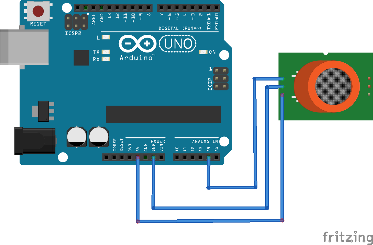
We need to load Arduino Sketch-2 to Arduino and interface GP2Y1010AU0F optical dust sensor, MQ-135 air quality sensor, and DC motor for assembling the project’s circuit with Arduino UNO. Extend the 5V output and Ground connections from Arduino UNO to a breadboard. For interfacing, the MQ-135 air quality sensor connects its VCC pin to Arduino’s 5V Out, GND pin to Arduino’s ground, and Aout pin to Arduino’s analog input pin A4, respectively.
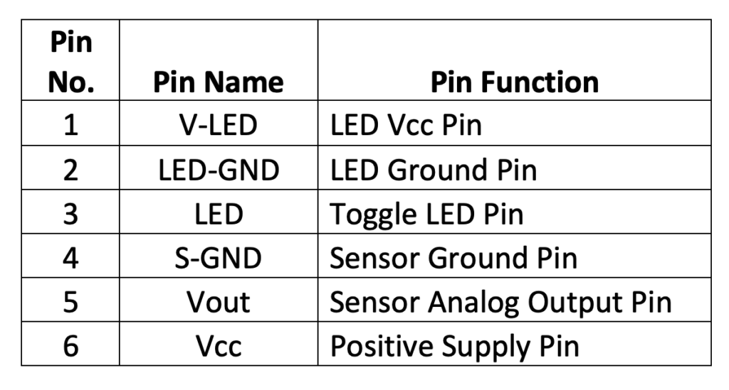
The GP2Y1010AU0F optical dust sensor has a six-pin connector with the following pin configuration.
 For interfacing GP2Y1010AU0F optical dust sensor with Arduino UNO, make the connections summarized in the table below.
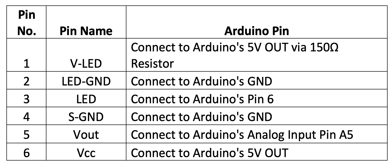
A DC motor connects the L293D Motor Driver IC for interfacing, as summarized in the table below.
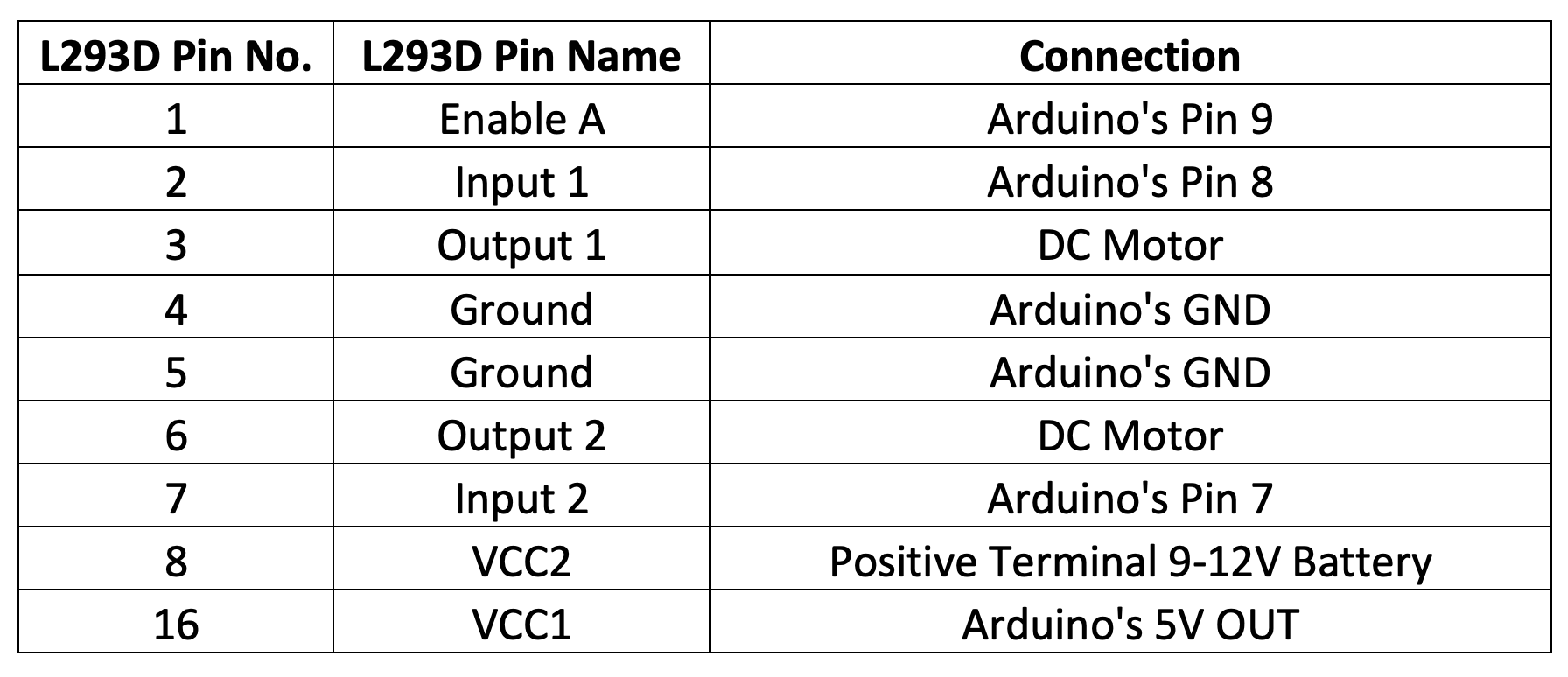
The above connections connect the negative terminal of the 9-12V battery with the Arduino’s GND making it a common ground between the Arduino and the L293D motor driver IC.
Arduino Sketch 1
Arduino Sketch 2
How it works
This circuit detects the air quality and dust density of the surrounding air and, according to measured values, actuate a car’s windows. To show the actuation of the car’s window, a DC motor is driven in the circuit. For measuring air quality, the MQ-135 sensor is used. The sensor is preheated for 24 hours to obtain the R0 value. The header file uses the value of R0 in the MQ-135 library. Once the actual R0 value is obtained, it is replaced with the default values in the MQ135.h file. The MQ135 library can be downloaded from this link.
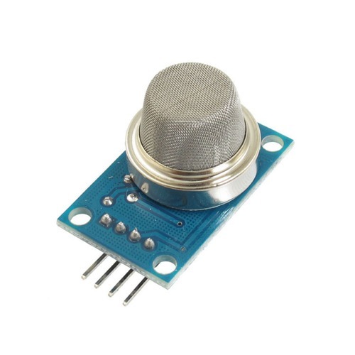 With a load resistance of 22KΩ, the MQ-135 sensor can measure the concentration of CO2 in the air. The sensor is connected to Arduino’s A4 pin. The concentration of CO2 in the air is obtained using the getPPM() function of the MQ135 library. If the concentration of CO2 is greater than 700 PPM, the car’s windows are closed by actuating the motor.
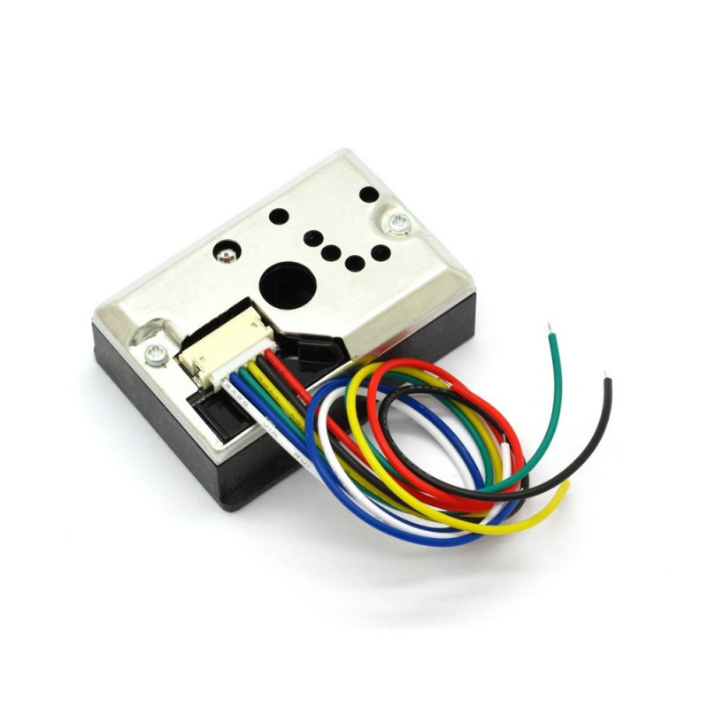
Simultaneously, the dust density is also measured by the circuit. Sharp’s GP2Y1010AU0F optical dust sensor helps detect fine particles like cigarette smoke and dust particles in the air. It consists of an IR diode and a photosensor that is assembled diagonally across an air inlet. When air containing dust particles enters the inlet, the dust particles scatter the IR radiations from the diode towards the photosensor. Greater is the dust density. More IR light is scattered, greater is the output voltage of the photosensor. The GP2Y1010AU0F sensor can detect dust particles as small as 0.5um and dust density up to 0.580 mg/m3. If the dust density is greater than 0.4, the car’s windows are closed by actuating the motor.
The Arduino is programmed to measure dust levels and concentrations of CO2 in the surrounding air. If either CO2 concentration is greater than 700 PPM or dust level is greater than 0.4 mg/m3, the Arduino drives the motor via L293D motor driver IC, and the windows are closed.
The code
For preheating the MQ-135 sensor, Arduino Sketch-1 is used. The sketch begins with importing the MQ135 library. In the setup() function, the baud rate for serial communication with Serial Monitor is set to 9600 bps. In the loop() function, analog reading from the MQ-135 sensor is read from pin A4, and the value of R0 is obtained using the getRZero() method. The obtained value is printed to the Serial Monitor. The value is observed after preheating the sensor for 24 hours in clean air. This value is obtained to be 929.15 for a load resistance of 22K. The values of load resistance and R0 are changed in the header file.
The Arduino Sketch-2 is loaded to the Arduino UNO for it working as the actual circuit. The sketch begins by importing the MQ-135 sensor library. This library can be downloaded as a Zip file from the above-mentioned link and imported by navigating to Sketch-> Include Library -> add .Zip library.
Next, the pins are assigned to connections with L293D Motor Driver IC. This is followed by pin connections to the dust sensor and declaration of variables to store calculations and value of dust level. Then, an object of the MQ135 library is instantiated, pins are assigned to connections with the MQ-135 sensor, and a variable to store the value of CO2 concentration is declared.
In the setup() function, the baud rate for serial communication with Arduino IDE’s Serial Monitor is set to 9600. This will be useful in monitoring CO2 concentration and dust level. The pins connected to L293D’s Enable A, Input 1, and Input 2 pins are set as a digital output. The DC motor is stopped, by default, by writing the LOW signal to Input 1 and Input 2 of L293D. The MQ135 sensor pin is set as input, and the pin connecting to the LED dust sensor is set as output.
A function drive_window() is declared, in which the DC motor is rotated to close the window for a short period of time. Then, the DC motor is stopped by writing a LOW signal to both Input 1 and Input 2 of L293D.
In the loop() function, first of all, dust level is calculated. The IR diode is turned ON for 280 microseconds for measuring dust level, and the output voltage from the photosensor is read. The process of reading output voltage from the dust sensor takes around 40 to 50 microseconds, so a delay of 40 microseconds is provided. According to the datasheet of GP2Y1010AU0F, the IR diode is pulsed every 10 milliseconds, so still, 9.68 milliseconds are left. The dust level is calculated using the following equations and printed to the Serial Monitor.
calcVoltage = voMeasured*(5.0/1024);
dustDensity = 0.17*calcVoltage-0.1;
Then, the analog reading from the MQ-135 sensor is obtained, and the value of CO2 concentration in PPM is calculated. If the CO2 concentration is greater than 700 PPM or dust level is greater than 0.4 mg/m3, the drive_motor() function is called.
Result
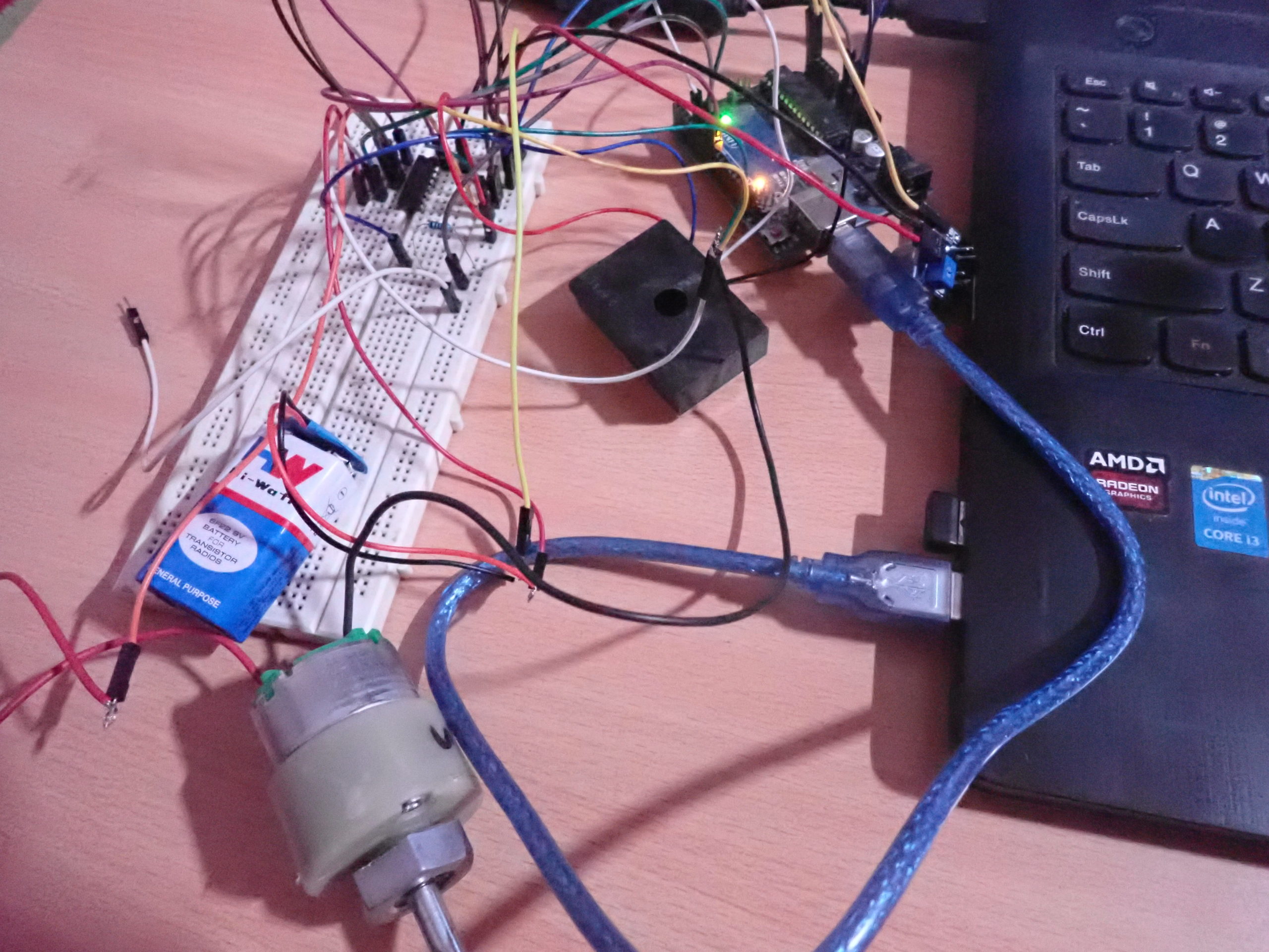
OLYMPUS DIGITAL CAMERA
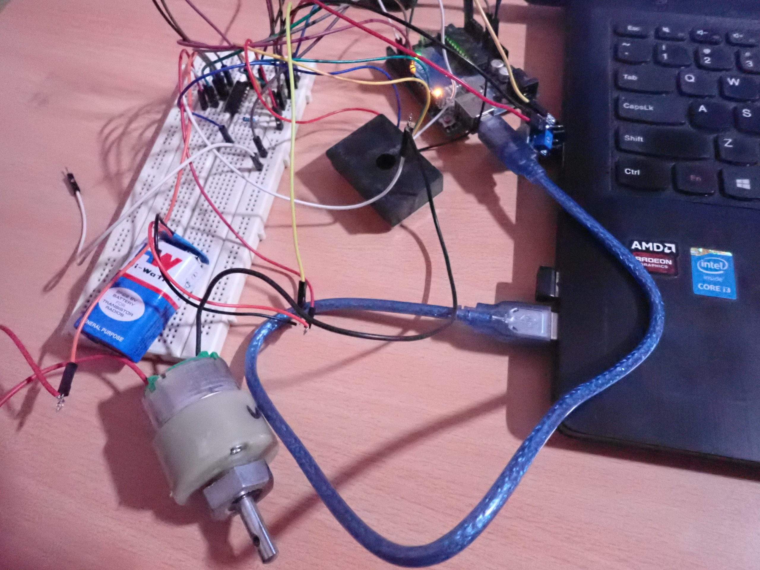
OLYMPUS DIGITAL CAMERA
You may also like:


Filed Under: Electronic Projects, Tutorials

Questions related to this article?
👉Ask and discuss on EDAboard.com and Electro-Tech-Online.com forums.
Tell Us What You Think!!
You must be logged in to post a comment.