Facial recognition technology identifies individuals by analyzing and comparing their facial features. It uses biometric patterns and algorithms to map and distinguish a person’s unique characteristics. The technology has become an essential component of many security applications.
Facial recognition is commonly used for access control, surveillance, biometric authentication, identity verification, criminal identification, attendance, emergency response, and fraud prevention.
What if you could build a facial recognition system for under $20? This is possible with an ESP32 camera. The ESP32-CAM module typically costs around US $10 (though prices may vary), and is capable of still pictures, video streaming, and facial recognition. In this project, we build a facial recognition system using the ESP32-CAM with Arduino.
Components required
- ESP32-CAM x1
- Arduino UNO or MEGA x1
- USB cable to connect Arduino with computer
- Jumper wires
ESP32-CAM
ESP32-CAM is a development board that combines the ESP32 microcontroller with a camera module, so it’s capable of capturing images and streaming video over Wi-Fi. It’s popular among developers and hobbyists for Internet-of-Things (IoT) applications and projects requiring a camera.
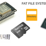
ESP32-CAM has a two-megapixel OV2640 camera and an onboard TF card slot. The camera supports JPEG and BMP image formats and several modes like single shot, burst, etc. The module is based on the Dual-core Tensilica LX6 microprocessor, a low-power 32-bit CPU. It has an integrated 4 MB flash memory for program storage and a MicroSD card slot can be used for additional storage. It has built-in WI-FI and Bluetooth, and the camera module can stream video over Wi-Fi.
 ESP32-CAM has the following pin diagram:
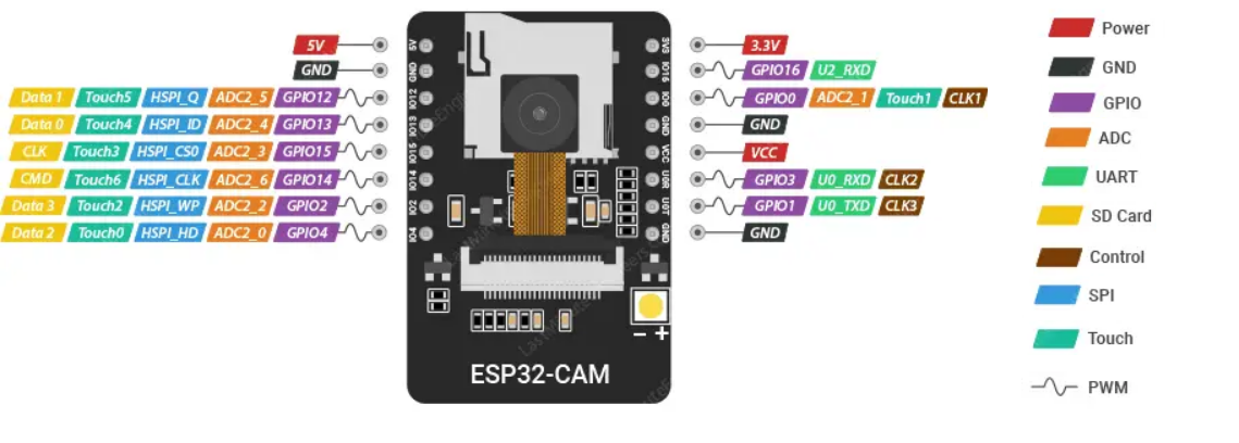
The module has two pins for power – 3.3 and 5V – and three ground pins. Two pins are for the universal asynchronous receiver/transmitter (UART) communication. It does not have a USB port, so the UART port must be used to upload code via an FTDI programmer or Arduino. When uploading code, the GPIO0 of the module must be connected to the ground.
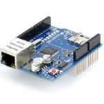
Circuit connections
For this project, we’ll use Arduino to upload the sketch to ESP32-CAM. Either Arduino UNO or Arduino MEGA works well.
The steps:
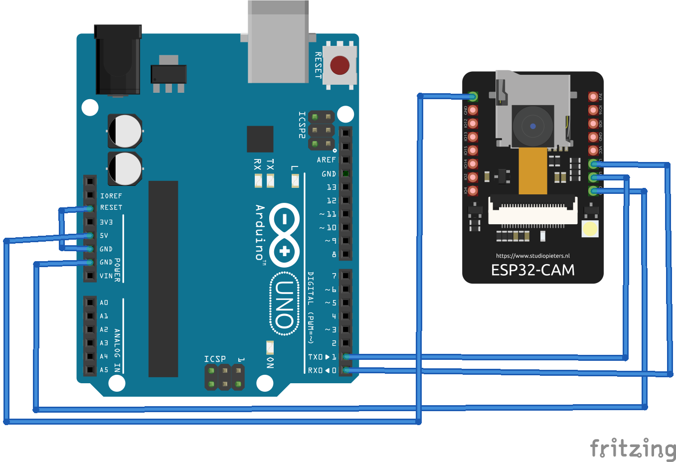
- Connect GPIO1 (U0_TXD) and GPIO3 (U0_RXD) with Arduino’s TX and RX pins
- Connect ESP32-CAM’s 5V and ground pin with Arduino’s 5V out and GND pins.
- Connect Arduino’s RESET pin to its ground pin.
- Upon uploading the sketch, connect ESP32-CAM’s GPIO0 with its ground pin.
- After uploading the sketch, remove the connection between ESP32-CAM’s GPIO0 and ground pins.
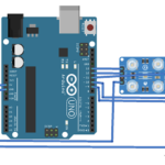
Circuit diagrams
This circuit diagram shows the connections between Arduino and ESP32-CAM when uploading the sketch.
 The following circuit diagram shows the connections between Arduino and the ESP32-CAM for the camera after uploading the sketch. Note, the connection between ESP32-CAM’s GPIO0 and ground pins are removed.
The sketch
Before uploading the sketch, you must install ESP32’s add-on and the ESP32 library in Arduino IDE. For ESP32’s add-on, navigate to File->Preferences, and add the following lines under the ‘Additional Board Manager URLs.’ Then, click ‘OK.’
https://raw.githubusercontent.com/espressif/arduino-esp32/gh-pages/package_esp32_index.json
Next, open the board manager by navigating to Tools-> Board -> Board Manager. Search for ESP32 and install ‘ESP32 by Espressif Systems.’
After installing the ESP32 add-on, navigate to File-> Examples -> ESP32 -> Camera, and open the CameraWebServer example. In the CameraWebServer example, you must disable ESP32-CAM’s Brownout feature. To do so, add the following libraries from the beginning of the example.
#include “soc/soc.h”
#include “soc/rtc_cntl_reg.h”
In the setup() function, add one more line of code as follows:
WRITE_PERI_REG(RTC_CNTL_BROWN_OUT_REG, 0);
In the example code, uncomment the following line of code:
#define CAMERA_MODEL_AI_THINKER // Has PSRAM
Replace the SSID and password assignments with the SSID and network key of your WI-FI connection. The complete sketch of the modified example is provided below.
#include “esp_camera.h”
#include <WiFi.h>
#include “soc/soc.h”
#include “soc/rtc_cntl_reg.h”
The code
Uploading the sketch
First, complete the circuit connections as instructed above for uploading the code. Remember, to connect ESP32-CAM’s GPIO0 with its ground pin to properly upload the sketch.
Connect Arduino with your computer using a USB cable. Select ‘ESP32 Wrover Module’ as the board and set the following parameters under ‘Tools.’
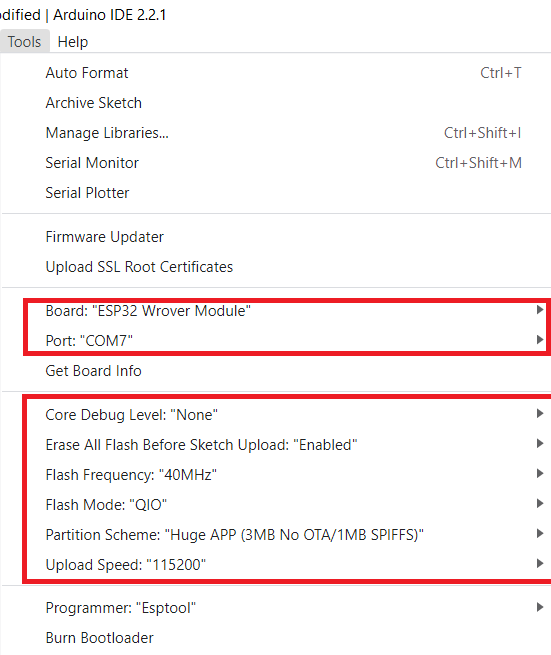
Compile and upload the sketch by clicking the upload button on Arduino IDE.
Get the IP address
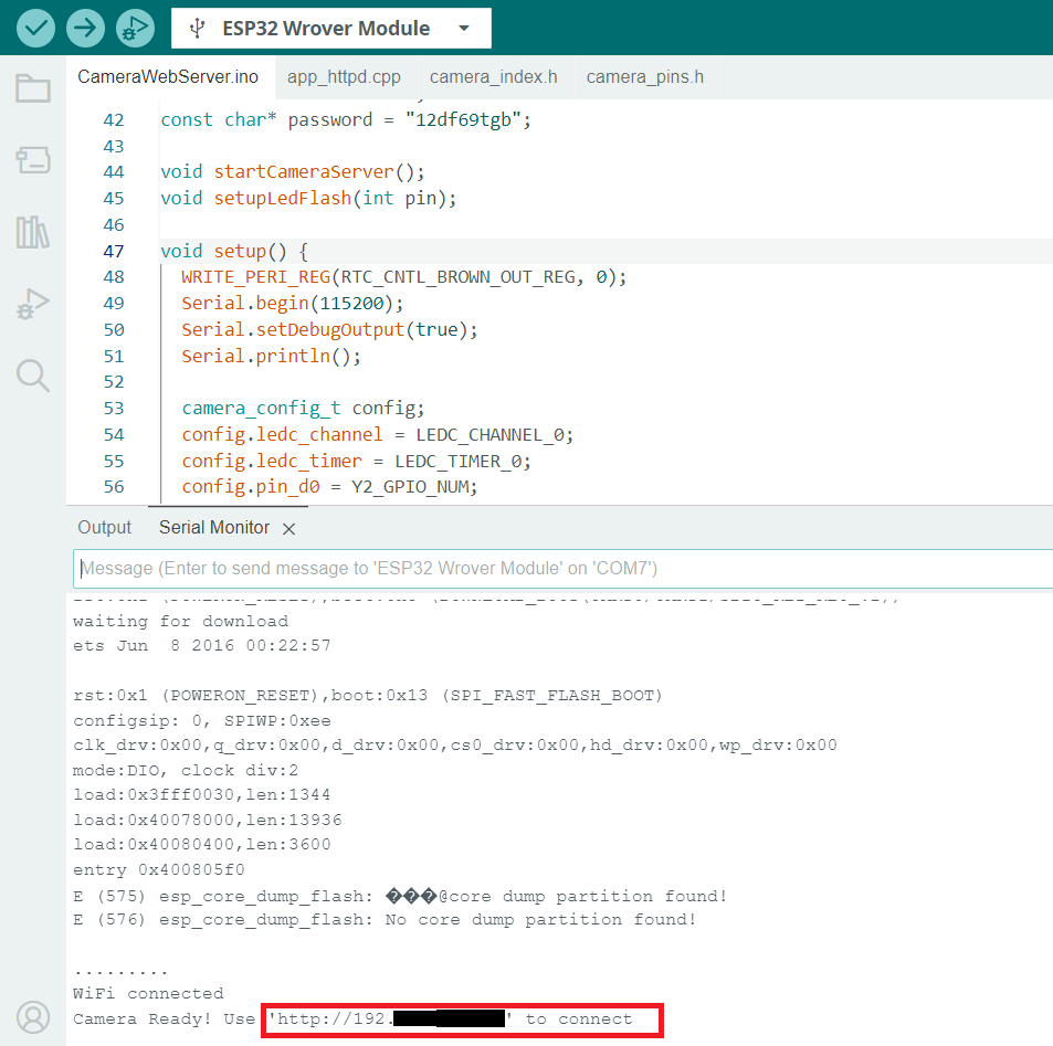
After uploading the code, remove the connection between ESP32-CAM’s GPIO0 and GND pins. Open Arduino IDE’s Serial Monitor and set its baud rate to 115200 bps. Press the reset button on ESP32-CAM and wait for the camera to connect with WI-FI.
After the camera is successfully initialized and connected to the Internet, the IP address that connects to the video streaming server will be printed on the Serial Monitor.
Accessing the video streaming server
Open the IP address obtained from ESP32-CAM in any Web browser. The video streaming server should open. Scroll down, and click ‘Start Stream.’
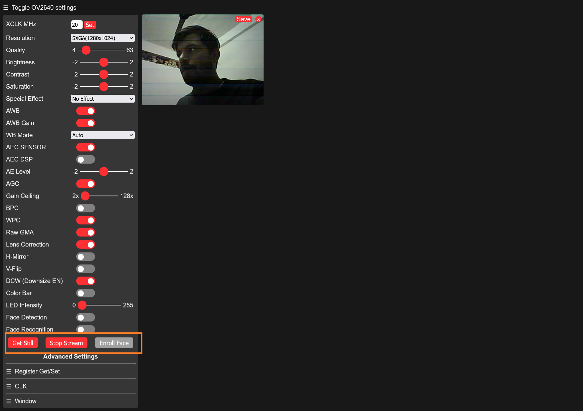
Here’s a video stream by ESP32-CAM over WI-FI.
You may also like:


Filed Under: Tutorials, Video

Questions related to this article?
👉Ask and discuss on Electro-Tech-Online.com and EDAboard.com forums.
Tell Us What You Think!!
You must be logged in to post a comment.