Proximity sensors are used to detect something approaching near. These sensors are useful in many applications like collision avoidance, obstacle detection, path following, touchless sensing, motion detection, and object detection. There are different types of proximity sensors like optical, ultrasonic, capacitive, inductive, and magnetic. The capacitive, inductive, and magnetic proximity sensors are used in specific electronic applications. The optical and ultrasonic proximity sensors have much general use and are quite common among electronics. These sensors come in a wide range according to their technology and distance of sensing.
The most simple kind of proximity sensor is the optical one. These proximity sensors are designed using active infrared sensors, consisting of a pair of IR source and an IR detector. The IR source can be either IR LED (Infrared Light Emitting Diode) or IR Laser Diode. The IR LED or IR Laser Diode transmits infrared light. This light is reflected by any object on which it falls. IR photodiodes that operate as IR detectors are placed in the sensor to capture the reflected IR radiations in a predefined range of distance and angle. Closer is the reflecting object; higher is the intensity of infrared radiation reflected, and lower IR photodiode resistance drops. As a result, IR photodiode passes through greater voltage than when there are no incident IR radiation.
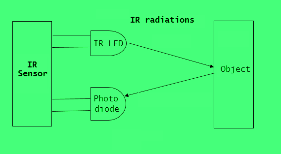
Working of active IR sensors
In this project, a proximity sensor built using IR LED and IR photodiode is used. The proximity sensors built using IR LEDs can sense objects at a short range of few centimeters. The sensor is interfaced with Arduino for application demonstration. In this project, we simply fast blink an LED as the sensor detects a near approaching object. The fast blinking of LED in this project indicates the possibility of a collision with the near approaching object. It gives a visual indication to the user to urge her to act quickly, avoiding a collision.
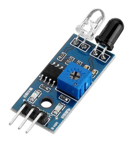
Example of IR proximity sensor
Components required
- Arduino UNO x1
- IR LED-Photodiode Module x1
- LED x1
- Resistor 330Ω x1
- Breadboard x1
- Connecting wires or jumper wires
Circuit connections
The commonly available IR LED-photodiode pair has three terminals – Ground, VCC, and Output. Connect the VCC and ground terminals of the IR module with 5V out and one of the ground channels of Arduino UNO. Connect the output of the sensor module to pin 2 of the Arduino. Connect the anode of a LED at pin 3 of Arduino UNO while connecting its cathode to the ground. Remember to place a current limiting resistor of 330Ω in series with the LED.
Circuit diagram
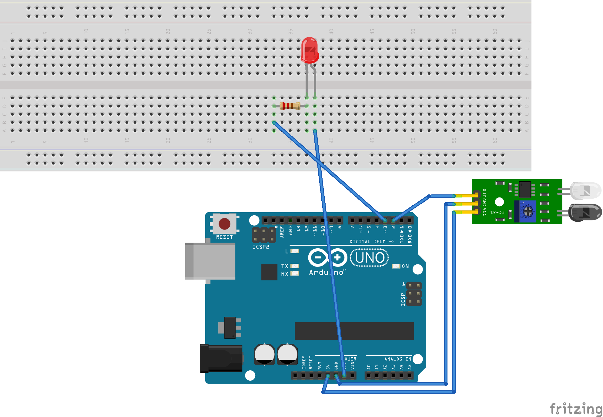
Circuit diagram of Arduino and IR LED based proximity sensor
Arduino sketch
unsigned int IRpin = 2;
unsigned int Indicatorpin = 3;
void blink_indicator(){
digitalWrite(Indicatorpin, HIGH);
delay(200);
digitalWrite(Indicatorpin, LOW);
delay(200);
}
void setup() {
pinMode(IRpin, INPUT_PULLUP);
pinMode(Indicatorpin, OUTPUT);
}
void loop() {
if(digitalRead(IRpin) == LOW) blink_indicator();
else digitalWrite(Indicatorpin, LOW);
}
How the circuit works
The IR LED is connected in forward bias in the sensor module. As 5V DC powers the module, the IR LED starts emitting IR radiations. An IR photodiode is placed parallel to the IR LED to detect the reflected radiations. The photodiode is connected in a voltage divider network, whose output goes to the inverting input of LM393 comparator IC. The non-inverting input of the same comparator is connected to a pot for adjustment of the reference voltage. The output of the comparator is taken as the output of the module.
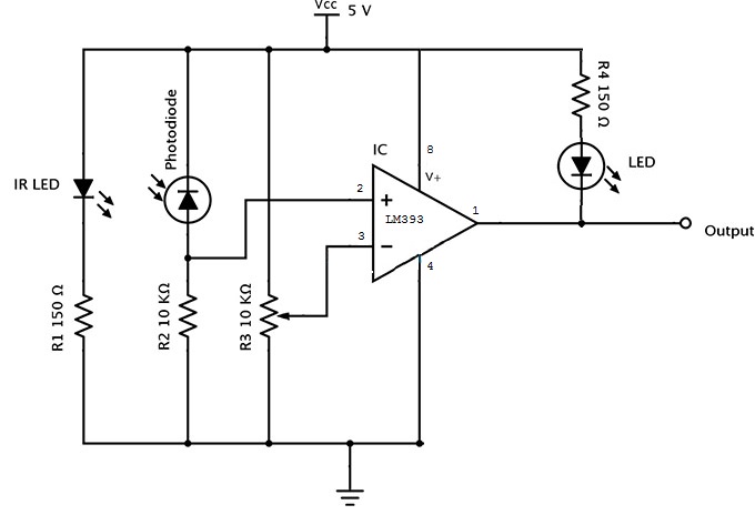
Circuit diagram of IR LED LM393 proximity sensor
When the IR detector receives reflected radiations, its resistance drops. As a result, a voltage higher than the reference voltage is applied at the comparator’s inverting input, and the comparator output turns to LOW.
Arduino is programmed to detect digital input from the IR module. As it detects a LOW logical signal from the IR sensor, it starts blinking LED connected at pin 3. When there is a HIGH logical signal from the IR module in the absence of any near approaching object, Arduino keeps the LED connected at pin 3.
How the code works
The Arduino sketch begins with pin assignment to the IR sensor and indicator LED. In the setup() function, the pin connecting the IR sensor is set to digital input, and the pin connecting indicator LED is set as output. A function blink_indicator() is defined to blink the LED at an interval of 200 milliseconds. In the loop() function, if a LOW is detected at the IR pin, blink_indicator() function is called. Otherwise, the LED pin is set to LOW, keeping the LED off.
Result
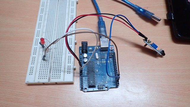
Circuit of Arduino and IR LED based proximity sensor
You may also like:


Filed Under: Arduino Projects, Electronic Projects, Sensor Series, Tutorials, Video
Log in to leave a comment:
Lost your password?
Don't have an account? Register here