Any AVR microcontroller based board which follows the standard arduino schematic and is flashed with the arduino boot-loader can be called an arduino board. The arduino is refered to as open source hardware, since the standard schematic is open to everyone and anybody can make their own version of arduino board following the standard schematic. All arduino boards should be compatible with the arduino IDE which can be used to program the arduino boards. The arduino IDE is also open source and anybody can contribute their libraries to the arduino. There is no other tool available which helps in easy prototyping like the arduino does. The arduino board has all the required circuitary to get the built-in AVR microcontroller running. The output or inputs can be taken from the boards or given to the board using convenient connectors. Both digital and analog inputs and outputs are available in all arduino boards. The arduino boards can also communicate with other devices using standard communication ports like USART, IIC, and USB etc. The most impressive thing is that most of the arduino boards are bread-board compatible which makes both the hobbyist and developers happy.
When it comes to programming the arduino board anyone who have basic knowledge of c programming can quickly get started with the arduino IDE. It is very simple to understand and has built-in functions for almost every simple or complex task. There are lots of libraries available which can be used to interface the arduino board with any other devices. One can hardly find a hardware module of which the interfacing code is not there in the arduino. Moreover there are lots of examples which can help one to get used with the arduino in a very short time.
This article discusses the steps required for getting started with arduino and explains how to code a simple LED blinking code.
Any AVR microcontroller-based board that follows the standard Arduino schematic and is flashed with the Arduino bootloader can be called an Arduino board. Arduino is referred to as open-source hardware since the standard schematic is open to everyone, and anybody can make their own version of an Arduino board following the standard schematic.
All Arduino boards should be compatible with the Arduino IDE, which can be used to program the Arduino boards. The Arduino IDE is also open-source, and anybody can contribute their libraries to the Arduino. No other tool is available that helps with easy prototyping like Arduino does. Its board has all the required circuitry to get the built-in AVR microcontroller running.
The output or inputs can be taken from the boards or given to the board using convenient connectors. All Arduino boards offer both digital and analog inputs and outputs. They can also communicate with other devices using standard ports like USART, IIC, USB, etc. The most impressive thing about them is that most of the Arduino boards are breadboard-compatible, making both hobbyists and developers happy.
When it comes to programming the Arduino board, anyone with basic knowledge of C programming can get quickly started with the Arduino IDE. It is very simple to understand and has built-in functions for almost every simple or complex task. Additionally, many libraries can be used to interface the Arduino board with any other devices. One can hardly find a hardware module without the interfacing code in the Arduino. There are many examples that can help you get used to using Arduino in a very short time.
This article discusses the steps required to get started with Arduino and explains how to code a simple LED blinking code.
Getting started
First, select the Arduino board that suits your requirements. Visit Arduino’s website to get all the details about the boards and software. Beginners are recommended to use the Arduino Duemilanove board or Arduino Uno board. Those used to handling hardware, soldering, etc., can choose the Arduino Pro-mini board. All details of available Arduino boards can be found on the website.
This article and its ensuing parts will explain the Arduino pro-mini board and the IDE version 1.0.3 for Windows. This board’s advantage is that it comes in a very small size — breadboard-compatible burg stick connectors can be soldered according to our requirements. It is very breadboard-friendly and occupies less space than a typical breadboard.
The only difficulty is that it requires another board to load the program into it through its USB port. The compatible USB to TTL converter board can be obtained from vendors or via online purchase. Together, these two boards cost less than other basic Arduino boards.
Downloading Arduino
The latest version of the Arduino IDE can be downloaded from the Arduino website itself. It is available for Windows, Linux, Mac, etc. Copy the entire folder to a preferred location on your PC, open the folder, click on the Arduino icon, and that’s it—no need to install.
The programming language is based on C, and anyone with a basic understanding of C should quickly be able to get started with it. If needed, a separate page discusses the details of the Arduino programming language.
If everything has been done correctly, the Arduino IDE will open, and it will look like Figure 4 in Windows.
Save the project in a folder selected to contain all projects and experiments with Arduino. Click file, Save As, select the required folder, and give the file a name. It is recommended for all the experiments with Arduino to create a folder named “ARDUINO WORKSPACE” and save this project as “_1_led_blinking.” Sketch names can only consist of ASCII characters and numbers (they cannot start with a number). They should also be less than 64 characters long.
The Arduino sketch is saved in the file format ‘.pde’ (Figure 5).
Coding
Now go to the examples and find the basic LED blinking code, as shown in Figure 6.
Now, in a separate window with the code opened, select all and copy-paste the entire code into the _1_led_blinking window. Close the new window with the ‘blink code’ left unedited (it is not supposed to be edited by the user because it is a working code and should be kept as such for future reference).
All the Arduino codes and hardware connections have a small description. The hardware connections are marked inside the green box shown in Figure 7 at the very beginning of the code file.
There is a built-in LED connection to the digital pin number 13 of the Arduino pro-mini board. This code is for blinking that LED with a delay.
An Arduino code has two basic functions, namely “setup ()” and “loop()”. The setup() is the function where all the initial settings, like setting the pin as input/output, initializing the serial communication with the baud rate, etc. The loop() is actually an infinite loop inside which the rest of the code should be written. The user-defined functions, if there are any, should be written separately outside the setup() and loop() and can be called from inside both of them.
The function pinMode() is a built-in function used to set a particular pin as input or output. The first parameter is the pin number, and the second parameter suggests whether the pin should be an input or output.
For example, to make pin number 5 as output:
pinMode (5, OUTPUT);
To make pin number 6 as input:
pinMode(6, INPUT);
In this particular example, the pin13 is already defined as LED using the statement:
int led = 13
Hence came the following statement:
pinMode(led, OUTPUT);
This can make the 13th pin of the Arduino board an output.
The digitalWrite() function is another function that can be used to write a digital value (logic 0 or logic high) to a particular pin that has already been made an output using the pinMode() function.
For example, to make the pin number 5 as logic high:
digitalWrite(5, HIGH);
To make the same pin as logic low:
digitalWrite(5, LOW);
The function delay () is very useful for almost all projects. It can generate a delay in milliseconds between code steps.
For example, to generate a delay of 5 seconds:
delay(5000);
Verifying the code
Once the coding has been done, it’s time to verify it. Arduino is so user-friendly that people usually don’t end up with too many errors. Use the button at the top left corner of the IDE, shown in Figure 8, for verifying the code:
Uploading to the board
Once the verification has been done, the code is ready to upload to the board. Connect the board to the PC’s USB port and install the driver that comes with it. After installing the driver, come back to the Arduino IDE and select the board from the list using tools>boards>Arduino pro mini (Figure 9).
After selecting the board, select the COM port on which it is connected, as shown in Figure 10.
Now, try to upload the code to the board by clicking the upload button shown in Figure 11.
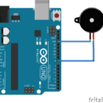
Refer to the code and circuit for blinking an external LED connected to pin number 5 of the Arduino board.
You can also try changing the delay or connecting an external LED to another pin and other basic things. No separate power supply is required, as the Arduino pro-mini board is USB-powered.
Conclusion
Arduino offers a simple and accessible platform for both beginners and advanced users. Getting started is easy with its open-source design, extensive libraries, and strong community support. The Arduino Pro Mini, while compact, is powerful and ideal for embedded projects. Users can quickly learn and advance to more complex applications by experimenting with basic projects like LED blinking.
You may also like:
Project Source Code
###
// Pin 5 has an LED connected on it through 1K resistor.
// give it a name:
int led = 5;
// the setup routine runs once when you press reset:
void setup() {
// initialize the digital pin as an output.
pinMode(led, OUTPUT);
}
// the loop routine runs over and over again forever:
void loop() {
digitalWrite(led, HIGH); // turn the LED on (HIGH is the voltage level)
delay(1000); // wait for a second
digitalWrite(led, LOW); // turn the LED off by making the voltage LOW
delay(1000); // wait for a second
}
###
Circuit Diagrams
Project Components
Project Video
Filed Under: Arduino Projects, Electronic Projects
Questions related to this article?
👉Ask and discuss on Electro-Tech-Online.com and EDAboard.com forums.
Tell Us What You Think!!
You must be logged in to post a comment.