An LED chaser or sequencer is a popular LED driving circuit. It’s used in running-light rope displays to flash different lighting patterns. In a chaser or sequencer circuit, a controller commands the sequence and timing of the flashing LEDs to illuminate different kinds of lighting patterns.
This LED chaser is built on Arduino UNO. Arduino is currently the most popular single-board microcontroller. In this sequencer, seven LEDs are interfaced with Arduino to demonstrate 13 different lighting patterns.
In fact, it’s possible to design an LED chaser with several LEDs by using shift registers. In this LED chaser, LEDs are directly interfaced to Arduino pins since Arduino’s GPIO can output forward voltage and the current required to switch them ON/OFF.
The LEDs are controlled via the digital output from Arduino. The UNO is programmed to output logical signals with different sequence over its pins with the appropriate timing pattern to show different LED light patterns.
Components required
1. Arduino UNO x1
2. LED x7
3. 330 Ohms Resistor x7
4. Breadboard x1
5. Male-to-Male Jumper Wires
Circuit connections
The circuit of this LED chaser is prototyped on a breadboard. LEDs are interfaced with the Arduino channels so that the channels sink the current from the LEDs. (To learn more about interfacing LEDs with Arduino, check out the LED interfacing tutorial).
Here are the instructions to properly assemble the circuit:
1. Connect the cathodes of the LEDs with the digital I/O pins 0, 1, 2, 3, 5, 6 and 7 from the Arduino UNO through the current-limiting series resistor at each channel.
2. Connect the anode of all of the LEDs to the power supplying row of the breadboard.
3. Load the sketch for the LED chaser to the Arduino.
4. Use the 5V power pin and one of the ground pins from Arduino to supply the 5V DC and then ground to the breadboard.
5. Switch ON the Arduino UNO by supplying power from either a USB or battery pack.
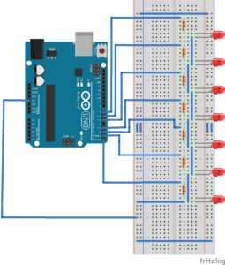
Circuit diagram

How the circuit works
Light Emitting Diodes (LEDs) are semiconductor diodes that emit light in a forward bias condition. These diodes are similar to signal diodes that are in functioning.
LEDs are distinguished by the range of wavelengths they emit. According to the bandwidth of light that’s emitted, they require different forward voltage to bias. The forward operating voltage for most of the LEDs varies from 1.2 to 3.6V, depending on their color.
Much like signal diodes, LEDs are also current-controlled devices and require between 12 to 30 mA for maximum illumination. For normal illumination, LEDs typically draw 5 mA of current.
Arduino’s GPIO can source or sink up to 40 mA of current. The voltage output of Arduino’s digital I/O channels is 5 and 3.3V for logical HIGH on 5 and 3.3V boards. The voltage level for logical LOW is 0V on both types of boards. The pins can sink the same voltage levels when configured as the input. So, LEDs can be directly driven by the Arduino’s I/O channels.
LEDs are two-terminal devices. This means they can be interfaced in a circuit in two ways. In one way, a device (such as Arduino’s channel) sources current to the LED. In this method of interfacing, the cathode of the LED is connected to the ground while the anode is connected to the current source.
In the second method, the device sinks current through the LED. In this method of interfacing, the anode of the LED is connected to the DC power supply rail and the cathode is connected to the current sink.
However, there must be a series resistor connected with the LED in both cases to protect the LED from overcurrent.
When the forward current is sourced or sinks through the LED, it switches ON and starts glowing. The forward current flows through the LED when it’s set to forward biased by applying the appropriate voltage. When the forward voltage is dropped or the reverse voltage is applied to an LED, it switches OFF and stops glowing.
In this circuit, seven LEDs are connected to Arduino UNO’s 0, 1, 2, 3, 5, 6, and 7 channels so that the pins must sink current through the LEDs. The red color LEDs are used in the circuit that requires a forward operating voltage of between 1.6 to 2V.
Resistors of 330 ohms are also connected to each LED in the series. With this value of a series resistor at each pin, Arduino’s channels must sink 9 to 11 mA of current when the LEDs are forward biased. (To learn more about interfacing LEDs with Arduino, check out the LED interfacing tutorial).
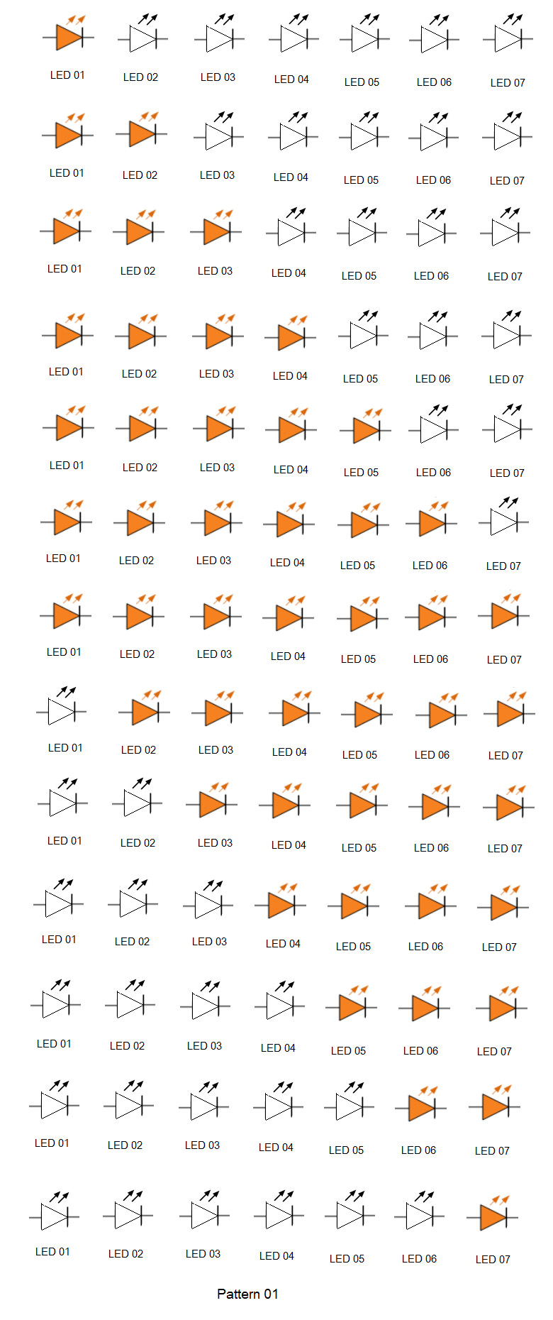
Remember, the chaser or sequencer is an LED driver circuit that operates LEDs based on a predetermined sequence and timing schedule. In this LED driver circuit, the controller (Arduino UNO) is programmed to flash 13 different lighting patterns. In the first lighting pattern, the LEDs are switched ON one after the other (from left to right) and then switched OFF one after the other (also from left to right).
A delay of 300 milliseconds is used when illuminating each LED and a delay of 200 milliseconds is used when switching them OFF.
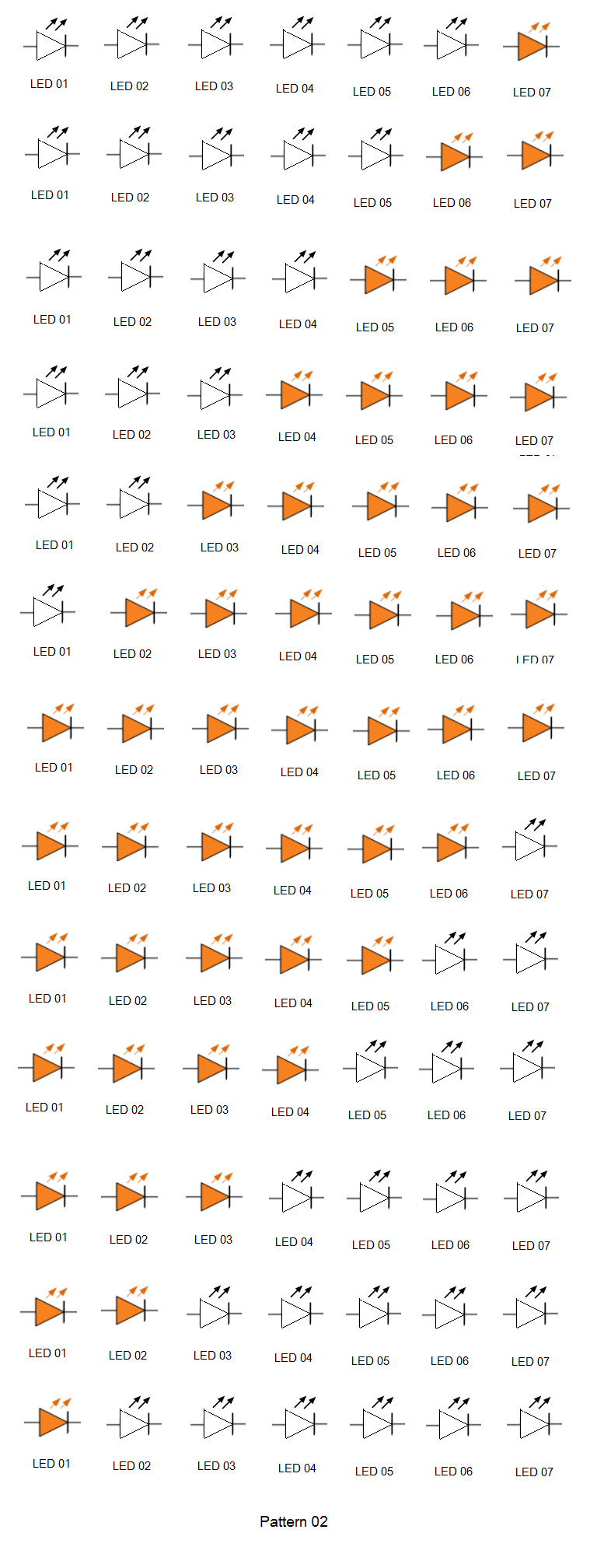
In the second lighting pattern, the LEDs are switched ON one after the other (from right to left) and then switched OFF one after the other (from right to left).
A delay of 300 milliseconds is used in illuminating each LED and a delay of 200 milliseconds is used in switching them OFF.
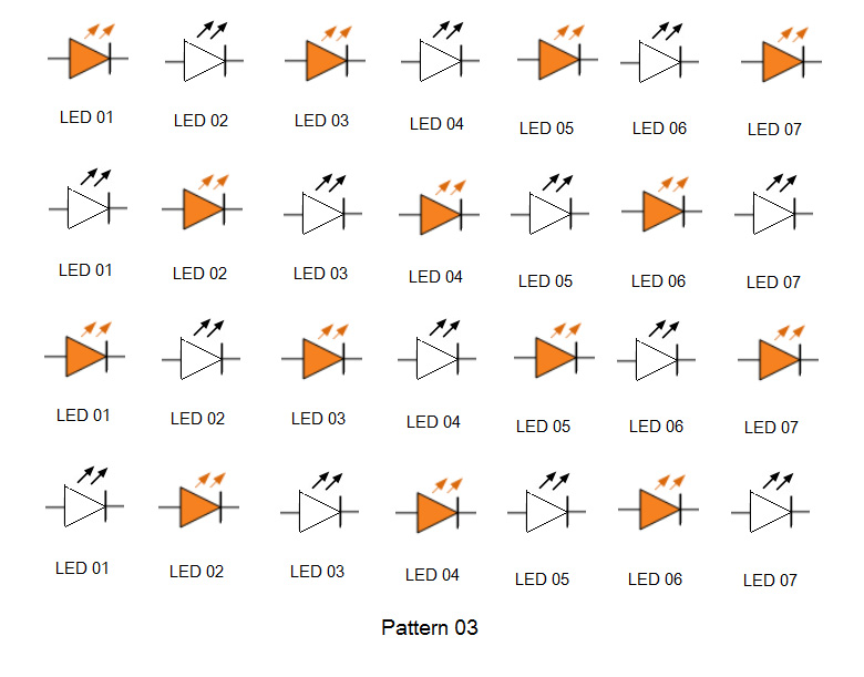
In the third lighting pattern, the odd LEDs are switched ON while the even LEDs are switched OFF. Then, the even LEDs are switched ON and the odd LEDs are switched OFF.
This pattern is repeated eight times before the LEDs all switch OFF. A delay of 300 milliseconds is used between each sequence.
In the fourth lighting pattern, the LEDs are switched ON one after the other (from left to right) and then they are switched OFF one after the other (from right to left).
A delay of 300 milliseconds is used in illuminating each LED and a delay of 200 milliseconds is used when switching them OFF.

In the fifth lighting pattern, the LEDs are switched ON one after the other (from right to left) and then they are switched OFF one after the other (from left to right).
A delay of 300 milliseconds is used in illuminating each LED and a delay of 200 milliseconds is used when switching them OFF.
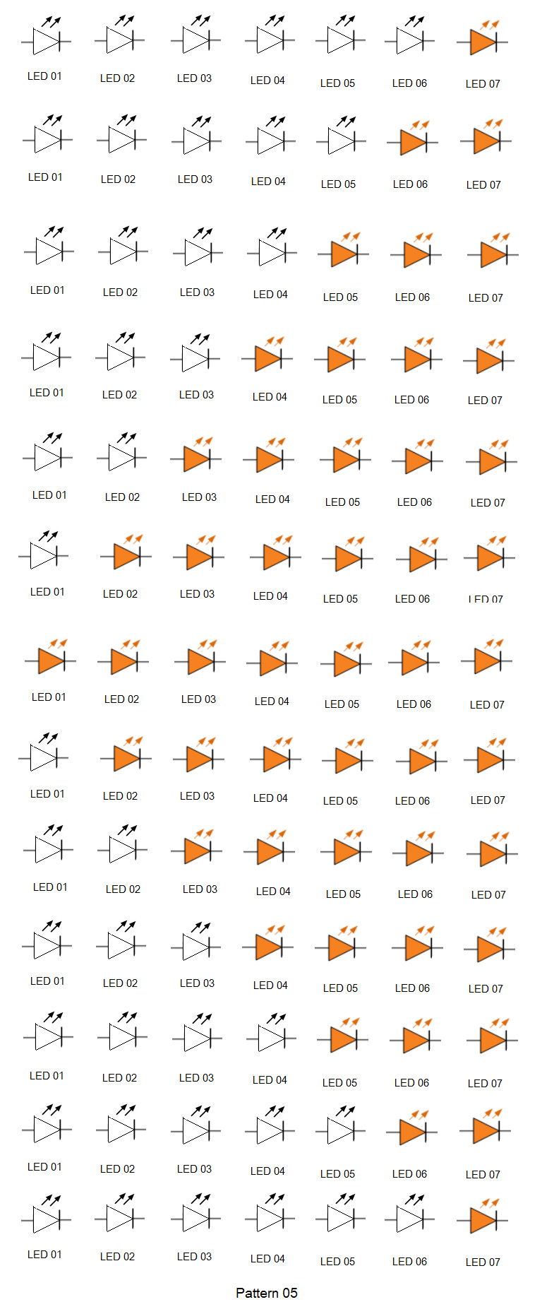
In the sixth lighting pattern, one LED from both sides is switched ON one after the other so that it slowly illuminates toward the center of the light rope. Next, it is switched OFF on both sides, fading to the center of the light rope. This pattern is repeated five times and a delay of 100 milliseconds is used between each sequence.
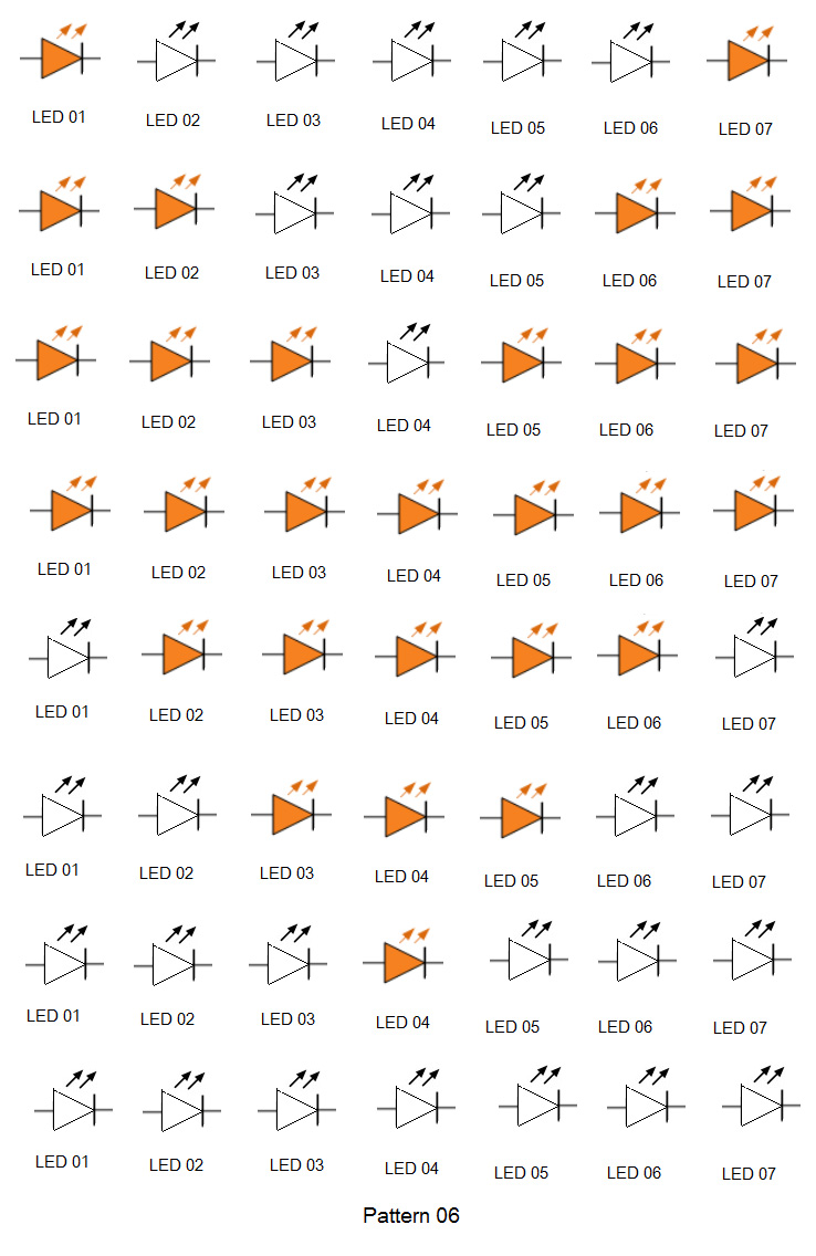
In the seventh lighting pattern, the LEDs are switched ON (from left to right) so the light moves toward the right of the light rope, one LED by one LED. After the light rope is fully illuminated, the LEDs are switched OFF (from left to right), one after the other.
A delay of 100 milliseconds is used between each sequence when illuminating the rope, while a delay of 200 milliseconds is used between each sequence when the lights are fading off.
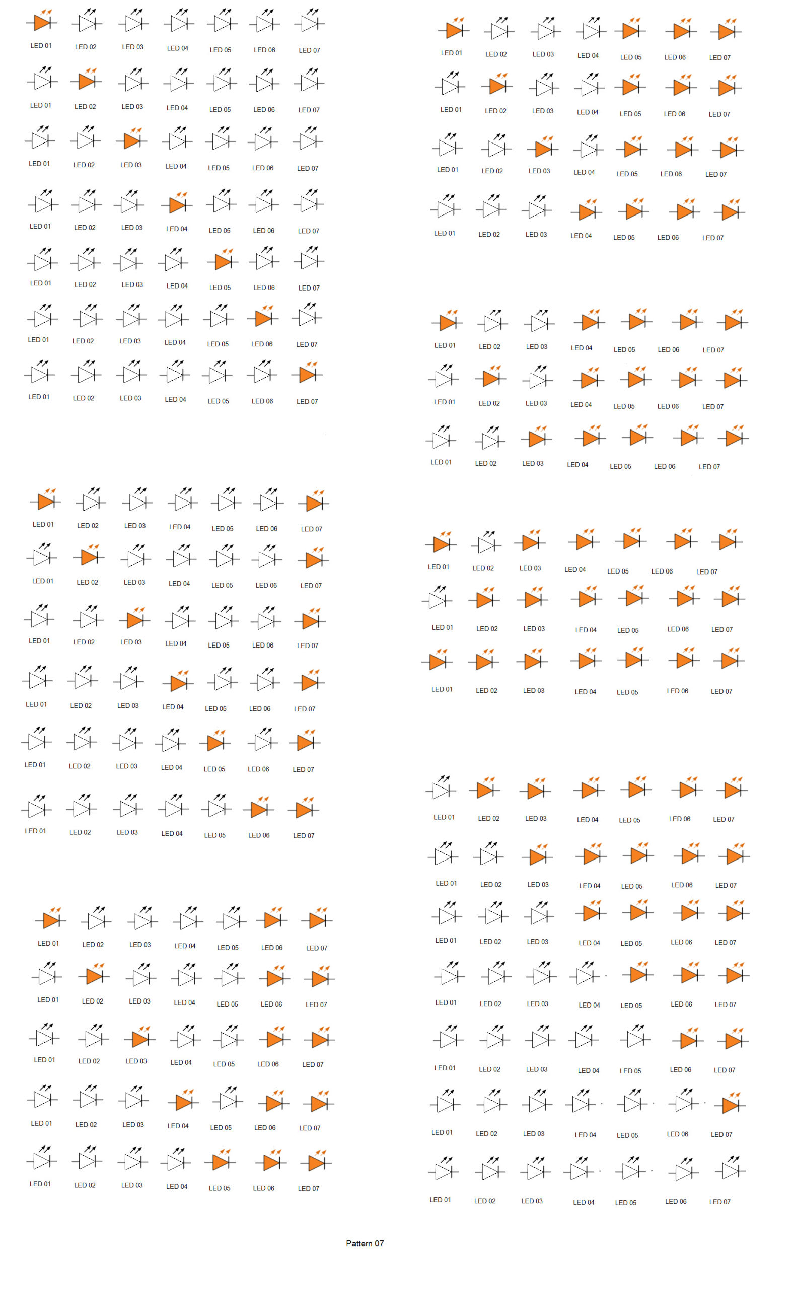
In the eighth lighting pattern, the LEDs are switched ON (from right to left) so that the light moves from the left of the light rope, one LED by one LED. After the light rope is fully illuminated, the LEDs are switched OFF (from right to left) one after the other.
A delay of 100 milliseconds is used between each sequence when illuminating the rope, while a delay of 200 milliseconds is used between each sequence when the lights are fading off.
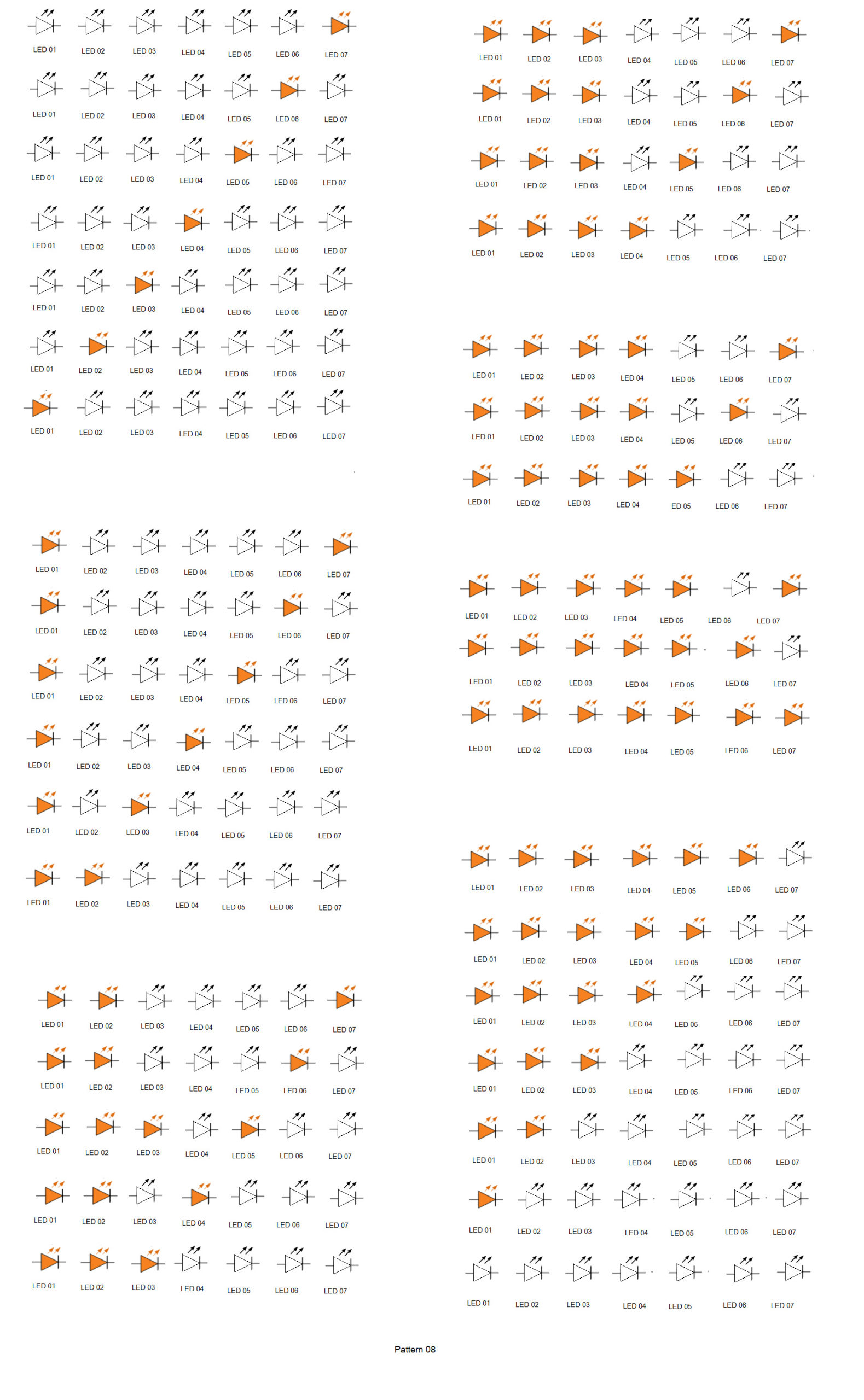
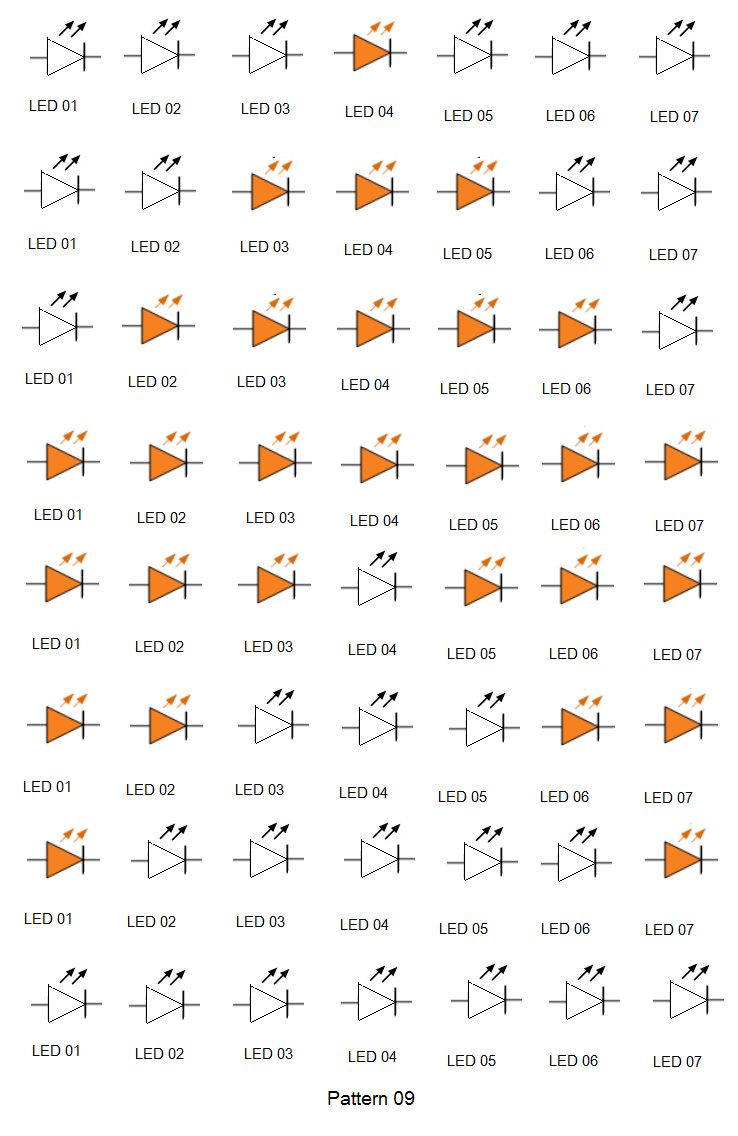
In the ninth lighting pattern, the LEDs are switched ON from the center and then toward both ends. Once the light rope is fully illuminated, the LEDs are switched OFF from the center toward both ends, simultaneously fading from the left and right sides.
This pattern is repeated five times with a delay of 100 milliseconds between each sequence.
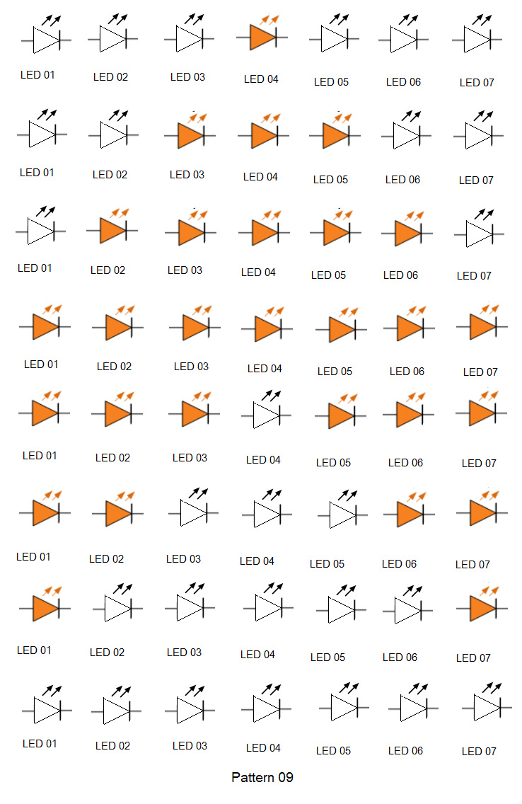
In the 10th lighting pattern, the LEDs are switched ON (from left to right) so that the light moves from the right of the light rope, one LED by one LED. After the light rope is fully illuminated, the LEDs are switched OFF (from right to left) one after the other.
A delay of 100 milliseconds is used between each sequence when illuminating the rope, while a delay of 200 milliseconds is used between each sequence when the lights are fading off.
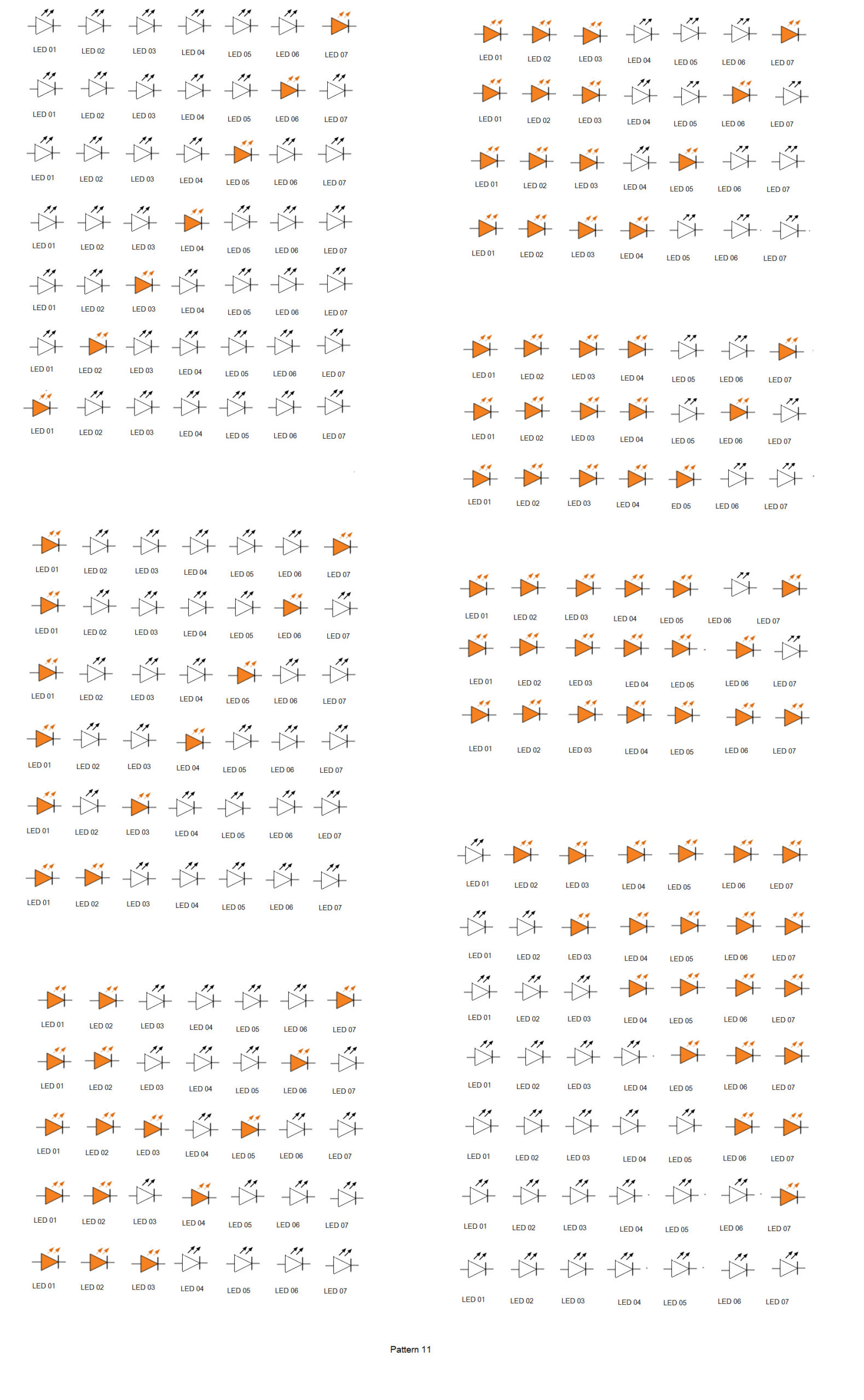
In the 11th lighting pattern, the LEDs are switched ON (from right to left) so that the light moves to the left of the light rope, one LED by one LED. After the light rope is fully illuminated, the LEDs are switched OFF (from left to right) one after the other.
A delay of 100 milliseconds is used between each sequence when illuminating the rope while a delay of 200 milliseconds is used between each sequence when the lights are fading off.
The lighting pattern six is repeated five times before illuminating the 12th pattern. In the 12th lighting pattern, the LEDs are switched ON (from left to right) so that the light moves to the right of the light rope, one LED by one LED. After the light rope is fully illuminated, the LEDs are switched OFF (from left to right) so that the fades from the right of the light rope, one by one.
A delay of 200 milliseconds is used between each sequence.
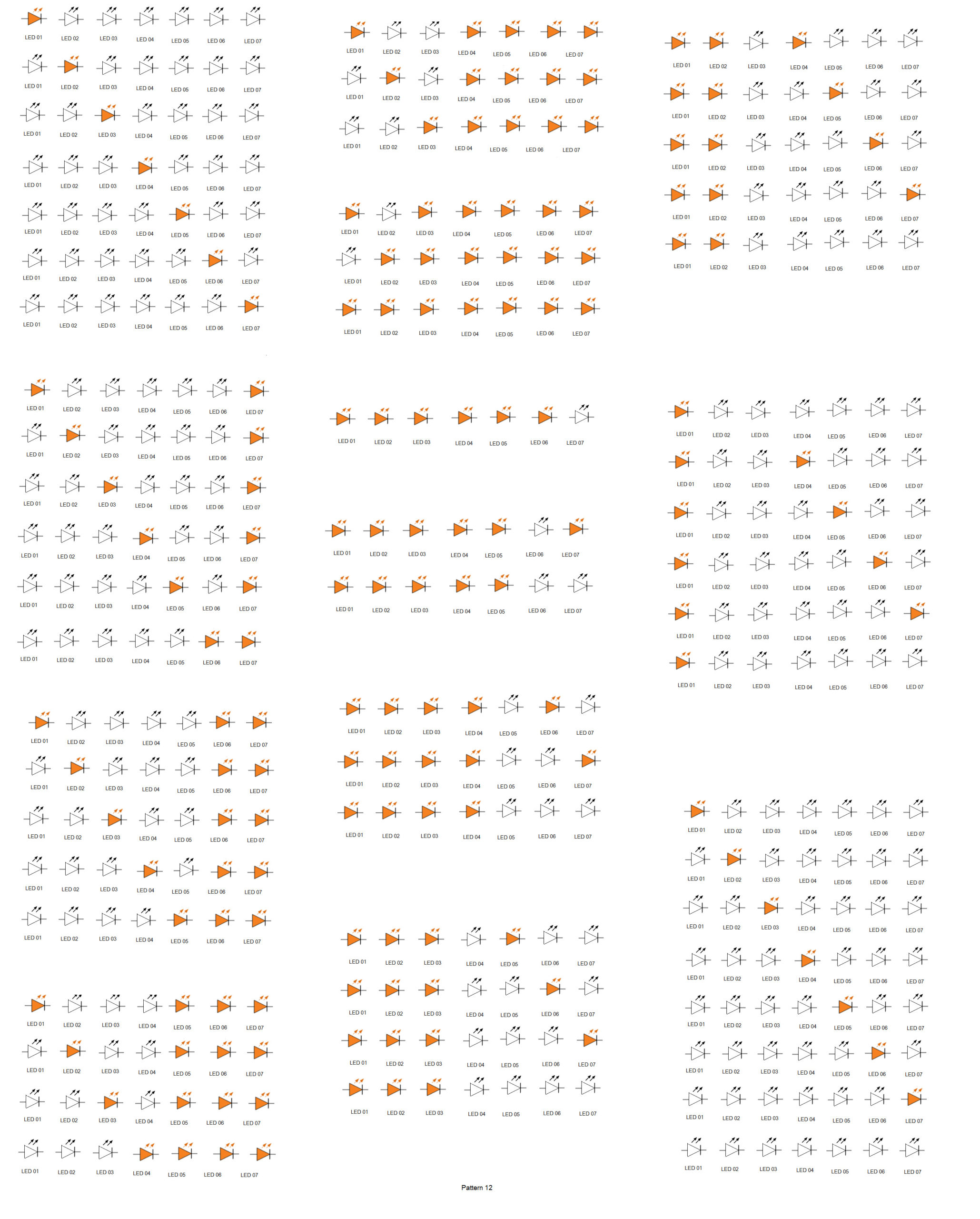
In the 13th lighting pattern, the LEDs are switched ON (from right to left) so that the light moves to the left of the light rope, one LED by one LED. After the light rope is fully illuminated, the LEDs are switched OFF (from right to left) so that the light fades from the left of the light rope, one by one.
A delay of 200 milliseconds is used between each sequence.
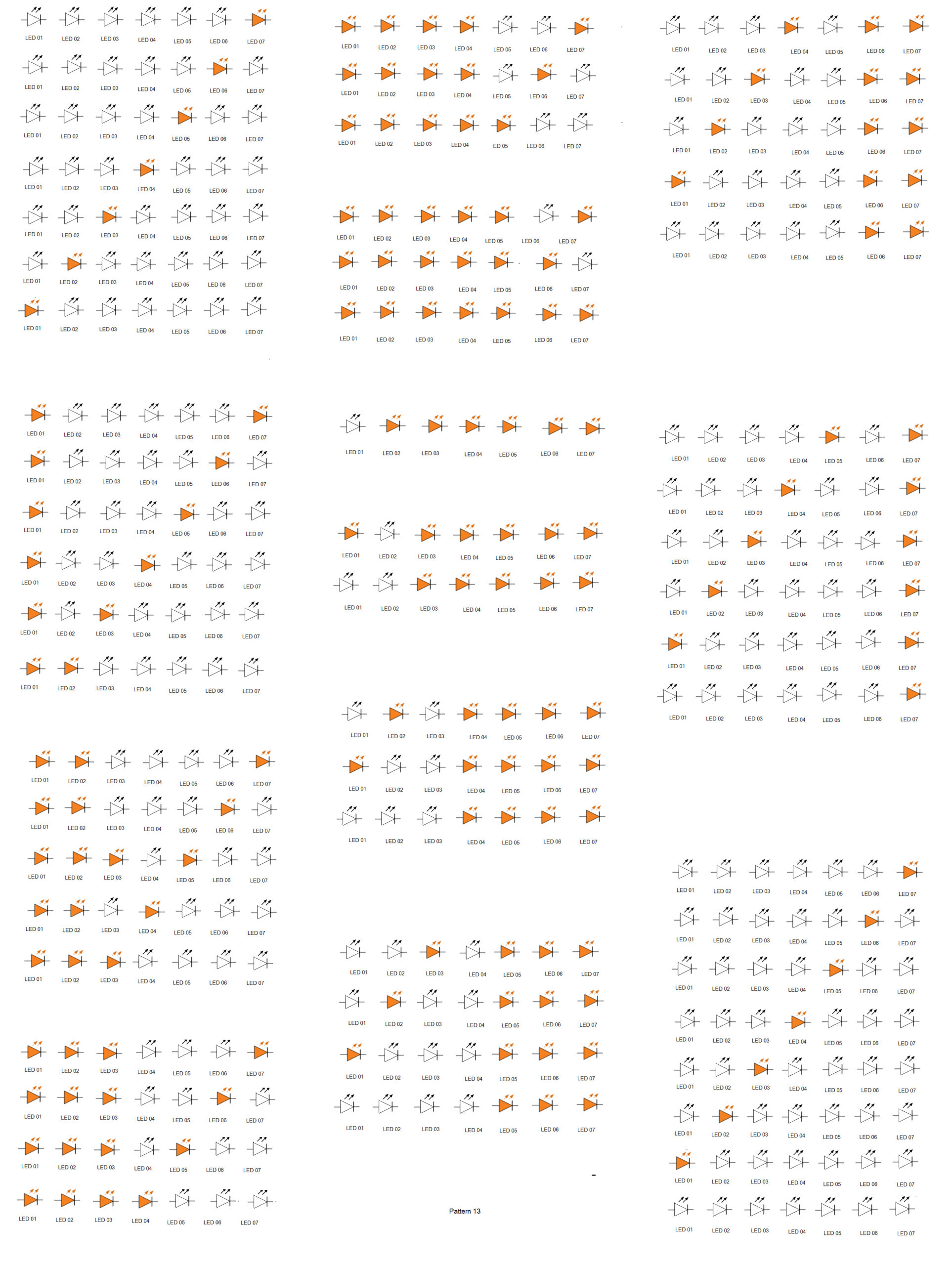
Finally, the ninth lighting pattern is repeated five times. Arduino will continue to repeat all of the lighting patterns for an infinite number of times until it’s powered ON. Whenever it’s reset or the power is resumed, it will start from the first lighting pattern.


Programming guide
The LEDs are interfaced with the Arduino’s pins such that the pins should sink current to forward bias them. The pins are configured as output using pinMode() function within the setup() function. The setup() function runs once when the Arduino boots up.
void setup() {
pinMode(0, OUTPUT);
pinMode(1, OUTPUT);
pinMode(2, OUTPUT);
pinMode(3, OUTPUT);
pinMode(5, OUTPUT);
pinMode(6, OUTPUT);
pinMode(7, OUTPUT);
}
When a logical LOW is set as the output from a pin, the current sinks through the interfaced LED and it glows. When a logical HIGH is set as the output from a pin, the interfaced LED is deprived of the required forward voltage and it will stop glowing.
The LEDs are interfaced to the Arduino UNO in this way:

When writing logical LOW or HIGH for Arduino’s I/O channels, the digitalWrite() function is used. To provide a delay between each sequence, the delay() function is used.
For example, the first lighting pattern is flashed by running the following code snippet:
//Pattern 01
digitalWrite(0, LOW);
delay(300);
digitalWrite(1, LOW);
delay(300);
digitalWrite(2, LOW);
delay(300);
digitalWrite(3, LOW);
delay(300);
digitalWrite(5, LOW);
delay(300);
digitalWrite(6, LOW);
delay(300);
digitalWrite(7, LOW);
delay(300);
digitalWrite(0, HIGH);
delay(200);
digitalWrite(1, HIGH);
delay(200);
digitalWrite(2, HIGH);
delay(200);
digitalWrite(3, HIGH);
delay(200);
digitalWrite(5, HIGH);
delay(200);
digitalWrite(6, HIGH);
delay(200);
digitalWrite(7, HIGH);
delay(200);
The code for all of the lighting patterns is written in the loop() function. This code keeps repeating for an infinite number of times, iterating through each lighting pattern until Arduino remains powered ON.
Whenever Arduino is reset or has resumed power after a shutdown, the code will starts from the setup() function. The complete sketch for this Arduino based LED chaser appears below the video.
Demonstration video:
You may also like:




Filed Under: Arduino Projects, Featured, Microcontroller Projects, Tutorials
Log in to leave a comment:
Lost your password?
Don't have an account? Register here