In the previous tutorial, we discussed magnetism, electromagnetism and inductance. Inductance can be useful in circuits. The electronic components that are designed to offer inductance in a circuit are called inductors.
Inductors
Most of the conducting materials (metals) are paramagnetic or ferromagnetic while most of the non-conducting materials (non-metals) are diamagnetic. Any conductor shows some inductance in response to change in magnitude or direction of the current. Even a simple straight wire shows some inductance, though it is small enough to be neglected in a circuit. If the same wire is wrapped in a loop, its inductance is increased. More the number of loops for the same length of wire, greater the inductance is shown by it. The inductance of a loop or coil of wire can be multiplied many times by using a suitable ferromagnetic core.
The simplest inductors are air-core coils. These are constructed by winding a coil of wire around plastic, wood or any non-ferromagnetic core. The inductance of a coil depends upon the number of turns, radius of the coil and overall shape of the coil. The inductance is proportional to the number of turns as well as the diameter of the coil. It is inversely proportional to the length of the wire for a given diameter and number of turns of the coil. So, closer will be the turns, greater will be the inductance. The current carrying capacity of the inductor depends upon the material and thickness of the wire. The operating losses (in the form of heat) from an inductor largely depend on the material used as a core in the inductor.
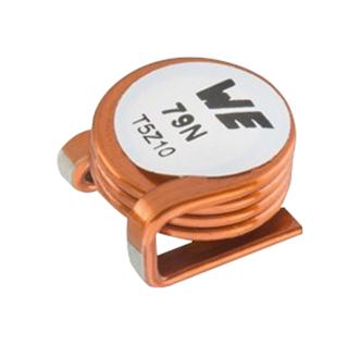
Example of air core inductor (Image: Wurth Electronics)
The air-core coils offer small inductances that can be a maximum 1 mH. The air-core coils can be designed to have unlimited current-carrying capacity by using heavy-gauge wire over a large radius. These inductors are almost lossless as air does not dissipate much energy in the form of heat. Higher is the frequency of AC current, less is the inductance required to produce significant effects. So, air-core inductors are quite suitable for high-frequency AC circuits due to lossless operation, high current capacity and sufficient inductance values.
By using powered iron or ferrite cores, the inductance can be significantly increased. However, the powdered iron or ferrite core also has a significant loss of electrical energy in the form of heat. The use of ferromagnetic cores also limits the current-carrying capacity of the inductor. With ferromagnetic cores, the inductance is saturated at a critical value of current. On increasing current beyond critical value, the inductance may, instead, starts decreasing. At high currents, the ferromagnetic cores may get enough hot that they may fracture and permanently change the nominal inductance of the inductor.
Solenoid vs inductors
Solenoids are often confused with the inductors. The solenoids are coils of wires that are intended to be used as electromagnets. Many inductors are also coils of wires but they are intended to offer inductance in a circuit. The inductors using cylindrical coils are also called solenoidal coils only because of their solenoid like construction. Though, they are not intended to be used as an electromagnet in a circuit. The solenoids are specifically used as electromagnets and usually have a moveable or static core. Commonly, solenoids are used as electromagnets in electric bells, DC motors, and relays.
Solenoidal coils as inductors
The simplest and most common inductors are solenoidal coils. These inductors are cylindrical coils wound around air-core or ferromagnetic core. These inductors are easiest to construct.
A solenoidal or cylindrical coil can be easily designed to vary inductance by incorporating a mechanism to slide in and out ferromagnetic core of the coil. By moving the core in and out of the coil, the effective permeability of the coil can be varied and so, the inductance of the coil. This is called permeability tuning. This is used to adjust frequencies in radio circuits.
The core can be made movable by attaching it to a screw shaft and fixing a nut at the other end of the coil. When the screw shaft is rotated clockwise, the core moves inside the coil increasing the effective permeability and so the inductance. When the screw shaft is rotated anti-clockwise, the core moves out, decreasing the effective permeability and so the inductance.
Toroids as inductors
Toroid is another most common form of inductors these days. Toroids have a donut-shaped ferromagnetic core on which the coil is wound. The toroids need fewer turns and are physically smaller for the same inductance and current-carrying capacity compared to solenoidal coils. Another major advantage with toroids is that the flux is contained within the core which avoids any unwanted mutual inductance.
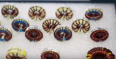
High-current toroidal conductors. (Image: Signal Transformer, a Bel Group)
However, it is difficult to wind the coil in a toroid. It is even much difficult to permeability tune a toroid. Designing variable inductors on toroid involves complex and cumbersome construction. The circuits where mutual inductance is wanted, the different coils need to be wound on the same core in case toroid is used as an inductor.
Pot cores as inductors
In typical inductors – solenoidal coils and toroids — the coil is wound around the ferromagnetic core. The pot core is another type of inductor in which the coil winding resides inside the ferromagnetic core. In pot core, the ferromagnetic core is in the form of two halves. The coil is wound and wrapped by one of the halves. The two halves have holes between them, from which the coil wire is taken out. The entire assembly is held together by a bolt and nut.
The pot cores like toroids offer large inductance and current-carrying capacity in small size with less number of turns. The flux, like in toroids, remains contained within the assembly. So, there is no unwanted mutual inductance with pot cores. Again, like in toroids, it is difficult to vary inductance in pot cores. It is only possible to vary inductance in pot cores by varying the number of turns and that by using taps at different points of the coil.
Transmission line as inductor
Inductors are mainly useful in AC circuits. For DC, inductors almost behave like a conducting wire offering some negligible resistance and nothing else. In AC, inductors find their actual applications. The audio frequency circuits generally use toroids, pot cores or audio transformers as inductors. The audio circuits typically use inductors of value ranging from few Milli-Henrys to 1 Henry. The inductors along with capacitors have been used in audio circuits for tuning. Nowadays, active ICs have almost replaced inductors and capacitors in audio circuits and applications.
As the frequency increases, inductors with lower permeability cores are used. At the lower end of radio frequencies, the same inductors that are used in audio applications are used. At radio frequencies up to few MHz, toroids are quite common. For radio frequencies from 30 to 100 MHz, air-core coils are preferred.
For radio frequencies greater than 100 MHz, transmission line inductors are useful. The transmission lines of short length (quarter wavelength or less of the signal wavelength) can be used as inductor for tuning high-frequency radio signals. The transmission line used as the inductor is generally coaxial cable.
Inductor in DC circuit
Practically, inductors are not useful in DC circuits as they will show no inductance for constant currents. However, assuming an inductor connected in a DC circuit can be useful in understanding its working principle and its behavior to pulsating DC voltages. Suppose a pure inductor is connected to a voltage source via a switch. When the switch is closed, the voltage is applied across the inductor causing a rapid change in current through it. As the applied voltage increases from zero to a peak value (in a short time), the inductor opposes the flow of changing current through it by inducing a voltage opposite in polarity to the applied voltage. The induced voltage during energizing of the inductor is called back EMF and is given by the following equation –
VL = – L*(di/dt)
Where,
VL is the voltage (back EMF) induced in the inductor.
L is the inductance offered by the inductor.
di/dt is the rate of change of current with respect to time.
A sudden change in current through the inductor gives infinite voltage, which is not feasible. So, current through the inductor cannot change abruptly. The current faces the effect of inductance for every small change in magnitude and slowly rises to its peak constant value. So, initially, the inductor acts as open circuit when the switch is closed. The back EMF remains across the inductor until the current is changing through it. The induced back EMF always remains equal and opposite of the rising applied voltage. As the voltage and current from the source approach a constant value, the back EMF drops to zero and the inductor acts as a short circuit like a connecting wire. While energizing, the power stored by the inductor is given by the following equation –
P = V * I = L*i*di/dt
Where,
P is the electrical power stored by the inductor.
V is the peak voltage across inductor.
I is the peak current through inductor.
The energy stored by the inductor while energizing is given by the following equation –
W = ∫P.dt = ∫L*i*(di/dt)dt = (1/2)LI2
Where,
W is the electrical energy stored by the inductor in the form of magnetic field.
I is the maximum current through it.
When the voltage source is removed (by opening the switch) the voltage across the inductor drops from peak constant value to zero. Unlike capacitors, on removing the voltage source, the voltage across the inductor is not retained. It, in fact, has already dropped to zero when current through it became constant. Now, as the applied voltage drops from peak constant value to zero, the current through the inductor also drops from constant peak value to zero. Now, the inductor opposes the drop in current by inducing a forward EMF in the direction of the applied voltage. Due to induced forward EMF, the current through the inductor drops to zero by a slower rate. Once the current reduces to zero, the forward EMF also drops to zero.
So, while energizing, electrical energy was converted to a magnetic field in the inductor which was evident by the back EMF induced across it. While de-energizing, the same electrical energy is given back by the inductor to the circuit in the form of forward EMF. Whenever voltage across the inductor increases, back EMF is produced and whenever voltage across the inductor decreases, forward EMF is produced.
Practically, the back EMF or forward EMF developed across an inductor is many times larger than the applied voltage. If only an inductor is connected with a voltage source or inductor is connected in a DC circuit without any protection, the electrical energy given back on opening the switch is released in the form of a voltage spike or spark at the switch contact. If the inductance is large or current in the circuit is high, the energy released in the form or arc or spark at the switch contact can even burn or melt it. This can be avoided by using a resistor and a capacitor (RC) network in series with the switch contact. This RC network is called Snubber Network. It let the electrical energy released by the inductor to charge and discharge the capacitor, so it does not damage any other component. In many circuits, protection diodes are used to save other components of the circuit from back or forward EMF of an inductor or solenoid.
Inductor in AC circuit
As the inductor opposes any change in current, the AC current lags by 90° to the AC voltage through the inductor. Initially, when the voltage from a source is applied to an inductor, the current through the inductor is maximum and in the opposite direction. As the voltage is applied, the current flows through the inductor due to back EMF induced opposite to the applied voltage. The induced voltage across the inductor is always equal and opposite to applied voltage at every point of time. As the applied voltage rises from zero to peak value, the opposing current through the inductor drops from maximum to zero.
When the applied voltage drops from peak value to zero, forward EMF is induced across the inductor causing the current through it to rise from zero to its peak value in the opposite direction. When the applied signal changes polarity and rises to peak value in opposite direction, again a back EMF is induced in the inductor causing the opposing current to drop from peak value to zero. As the applied voltage again drops to zero to reverse direction, a forward EMF is induced in the inductor causing the current to rise again from zero to its peak value in the opposite direction. This continues for each cycle of the AC signal.
Inductive reactance
The opposition to current due to inductance is indicated by inductive reactance. The amplitude of the current through the inductor is inversely proportional to the frequency of the applied voltage signal. As the voltage across the inductor (back EMF or forward EMF) is proportional to inductance, the amplitude of the current is also inversely proportional to the inductance. So, the opposition to current due to inductance in the form of inductive reactance is given by the following equation:
XL = 2πfL
= ωL
Accordingly, the peak amplitude of the current through the inductor is given by the following equation:
Ipeak = Vpeak/XL
= Vpeak/ ωL
Where,
Ipeak is the peak value of AC current through the inductor.
Vpeak is the peak value of AC voltage applied to inductor.
XL is inductive reactance.
Like resistance and capacitive reactance, the unit of inductive reactance is also ohms. It should be noted that there is no loss of energy in a circuit due to capacitive or inductive reactance, unlike resistance. However, reactance can limit the current levels through the capacitor or inductor.
Applications of inductors
The inductors are used with AC circuits. They are commonly used in analog and signal processing circuits in telecommunications. They are also used along with capacitors to design filter circuits. In telecommunications, inductors are also used to depress system voltages or fault currents along transmission lines. By coupling inductors, transformers are designed that are used to step up or step down AC voltages. Inductors are also used to store electrical energy temporarily in SMPS and UPS circuits. In power supply circuits, inductors (where they are called filter chokes) are used to smooth pulsating currents.
The signal behavior of an inductor can be summarized as follows:
- Whenever applied voltage to an inductor increases, back EMF is generated by the inductor causing the current through it to drop from a maximum value to zero or lower level. Whenever applied voltage decreases, forward EMF is produced by the inductor causing the current through it to rise from zero or current level to a maximum value or higher level.
- The back EMF or forward EMF remains across the inductor until the applied voltage and so the current through it is changing. As the applied voltage saturates to a constant value, back EMF or forward EMF is dropped to zero and a constant current flows through the inductor without any opposition like in a connecting wire.
- Due to inductance, the rate of change of current is slowed in the circuit. If the signal is AC, the current will always lag voltage by 90° due to inductance.
- Due to inductive or capacitive reactance, there is no loss of energy. The energy stored by an inductor in the form of magnetic field or by a capacitor in the form of electrostatic field is returned back to the circuit as the applied voltage drops or reverse direction. However, due to reactance, the peak current level (amplitude of the current signal) is limited.
In the next article, we will discuss various non-ideal characteristics and key performance indicators of inductors.
You may also like:
Filed Under: Tutorials





Questions related to this article?
👉Ask and discuss on EDAboard.com and Electro-Tech-Online.com forums.
Tell Us What You Think!!
You must be logged in to post a comment.