In a previous article, we discussed various types of fixed resistors, selection of resistor type for a given circuit, and identifying value, tolerance and power rating of fixed resistors. Let’s now talk about variable resistors.
The resistance of variable resistors can be adjusted manually or digitally. The variable resistors offer a range of resistance instead of a fixed resistance that can be either controlled through linear or rotary motion otherwise digitally. Compared to fixed resistors which commonly have 5% tolerance, variable resistors usually have around 20% tolerance, which means that the range of resistance offered by variable resistors usually varies 1.2 times the rated range of resistance.
The variable resistors which are used for varying voltage division are called potentiometers. Small potentiometers are called trimpot or trimmer potentiometer. The potentiometers in which resistance is varied digitally instead of by mechanical movement are called digital potentiometer. The variable resistors that are used to vary the resistance in order to control current in a circuit are called rheostat. There are four primary types of variable resistors:
1) Potentiometer
2) Trimpot
3) Digital Potentiometer
4) Rheostat
Potentiometers
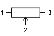
Potentiometer — also known as “pot'” — is the most common type of variable resistor. A potentiometer is generally a three-terminal device of which resistance can be manually adjusted. It has a resistive track between the first and third terminal. The second terminal remains connected to a wiper which contacts the resistive track between the first and third terminal. The wiper can be moved either through rotary or linear movement. This way potentiometer actually creates a voltage divider network in which the ratio of resistance between first to second and second to the third terminal can be adjusted and so the output voltage at the second terminal. So, a potentiometer can be seen as two resistances connected in series with connections to end terminals and the junction(s) where the ratio of resistances can be manually adjusted. The potentiometer has the following IEC standard symbol:
The resistance at the adjustable terminal when wiper enters the resistive path is called Hop-on Resistance. The resistance at the adjustable terminal when the wiper exits the resistive path is called Hop-off resistance. The difference between the hop-on and hop-off resistance is the Total Resistance of the potentiometer. The smallest possible change in the resistance ratio of the potentiometer is called its Resolution. The resolution of potentiometers is often increased by increasing the number of contact points of the wiper with the resistive path. The relationship between the mechanical position and resistance ratio of the potentiometer is called Potentiometer Taper.
The potentiometer taper can be either linear or logarithmic. In linear taper, the ratio of resistance changes linearly relative to the position of the wiper. So, if the wiper is at the center of the resistive track of a linear taper potentiometer, the output voltage is half of the applied voltage. The linear taper is commonly used as a transducer for measurement of distance or angle. In logarithmic taper, the ratio of resistance changes non-linearly by a logarithmic scale relative to the position of the wiper. Actually, in logarithmic potentiometers, the change in resistance ratio occurs exponentially. The logarithmic taper is commonly used for volume control in audio circuits. That is why it is also called Audio Taper.
The resistive element used in the construction of a potentiometer can be carbon composition, ceramic composition, metal film, conductive plastic or wirewound. The potentiometers based on carbon composition are the most commonly available. These potentiometers are constructed by molding carbon composition mixture on a ceramic substrate. The carbon composition based potentiometers have the same advantages and drawbacks as of the carbon composition fixed resistors. For better stability and temperature tolerance, Cermet based potentiometers can be used. However, Cermet based potentiometers are expensive and have low lifespan. Cermet Pots with guaranteed long life also come available but they are even more expensive.
For a long lifespan, conductive plastic-based potentiometers fit the bill. These potentiometers have high resolution, low noise, smooth handling and can be adjusted millions of times. These potentiometers have notably the best resolution. For high power and high precision applications, wirewound potentiometers are most suitable. However, wirewound potentiometers have a rough handling and limited resolution. The resolution of wirewound resistors is usually in discrete values due to discrete number of wire turns.
Types of potentiometer
The potentiometers come in a variety of designs and constructions. They are divided mainly into the following two types: rotary potentiometers and linear potentiometers.
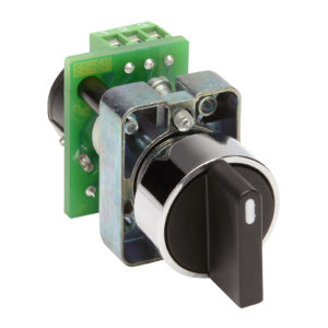
1) Rotary Potentiometers – In rotary potentiometers, the wiper moves along a circular path from one position to another separated 270 or 300 degrees. These are most commonly used potentiometers and can have an either linear or logarithmic taper. The rotary potentiometers come in a variety of constructions like as follows:
- a) Single Turn Pots – These are 3-terminal rotary potentiometers with a single rotation of 270 or 300 degrees. These pots have limited resolution and are most commonly used.
- b) Multi-Turn Pots – These pots have multiple turns (often 5, 10 or 20) for high resolution and precision. In these pots, the wiper moves along a spiral resistive track or using a worm gear.
- c) Dual Gang and Stacked Pots – These pots have two potentiometers combined on a single shaft. These pots are generally used in circuits where two pots are required but PCB has limited space or size. Generally, both the potentiometers are single turn pots having same resistance and taper. There are pots with more than two gangs but they are rarely used. Such pots are called stacked pots. The dual pots are commonly used in Hi-fi amplifiers and cascaded amplifier stages.
- d) Concentric Pots – These are dual gang pots where each potentiometer is adjusted by an individual concentric shaft. This allows controlling both potentiometers independently. These pots are commonly used sound equipment like bass guitars.
- e) Servo Pots – These are motorized pots that can be adjusted by a servo motor.
- f) Single Switch Push/Pull Pots – These are single turn pots with inbuilt ON/OFF switch to either completely cut off voltage or provide voltage division. The switch may be depressed (push) or lifted (pull). These pots come available in push-push or push-pull configuration. The push-push configuration pots however easily suffer from wear and tear.
- g) Double Switch Push/Pull Pots – These are single turn pots with two ON/OFF switches to either completely cut off voltage at two lines simultaneously or regulate voltage equally on two lines. These pots are commonly used for short circuit protection with phase and neutral wire connections in a circuit.
- h) Push/Pull Pots with Tap – These are 4-terminal single turn pots with two wiper terminals of which one wiper (usually Centre Tap) remains fixed to the resistive track. These pots have been used in audio circuits for tone control.
2) Linear Potentiometers – In linear potentiometer, the wiper moves along a linear resistive track. These pots are also called slider, fader or slide pot. The linear potentiometers come in a variety of constructions like as follows:
- a) Slide Pots – These are simple linear potentiometers often constructed of conducting plastic. These are often used as faders in audio circuits and systems or for measurement of distance.
- b) Dual-slide pot – These have two potentiometers controlled by a single slider. These pots are commonly used for stereo control in audio circuits.
- c) Multi-turn Slide – These pots have multiple turns (often 5, 10 or 20) for high resolution and precision. In these pots, the wiper moves along a spiral resistive track.
- d) Motorized Fader – These are single slide pots which can be controlled by a servo motor. These pots are commonly used for automatic control of resistance or voltage.
Key performance indicators of potentiometer
Like fixed resistors, potentiometers also have properties or KPIs. The important KPIs associated with potentiometers are as follows:
Nominal Value/Impedance – This is the total resistance of the potentiometer. The potentiometers generally have constant resistance near the first and third terminals. Their resistance varies over 5% to 95% along the resistive path. This is called electrical travel of the potentiometer.
Tolerance – Most of potentiometers have 20% or more tolerance. This tolerance applies to the range of resistance offered by the potentiometer, so more tolerance means that the potentiometer actually offer wider range of resistance.
Taper – The potentiometers can have either linear taper or logarithmic taper. Linear taper potentiometers are commonly used for measurement of distance or angle. They are also commonly used for voltage division. The logarithmic taper pots are commonly used in audio circuits. The taper of a potentiometer is indicated by its resistance curve.
Linearity – Linearity refers to deviation of actual resistance offered by the potentiometer from its resistance curve. This should be as low as possible. A potentiometer with low linearity will offer resistance much accurately as per its resistance curve. So, its resistance relative to the position of wiper will be much predictable.
Standard values of potentiometers
The potentiometers of any value are possible. However, potentiometers of preferred values like 1k, 5k, 10k, 20k, 22k, 25k, 47k, 50k and 100k are most common. For most of the regular circuits, 10k pot is sufficient.
Identifying properties of a potentiometer
The potentiometers generally have their total resistance and taper printed on them. The total resistance may be indicated by a string (10K) or by three-digit numerical code used for SMD resistors. The taper of the pot is usually indicated by a string or a designated character according to the region as follows:
| Taper | String | Asia | Europe | America | Vishay |
| Linear | LIN | B | A | B | A |
| Log/Audio | LOG | A | C | A | L |
| Anti-Log | – | – | F | C | F |
For studying other properties like linearity, impedance and resistance curve, etc, consult the manufacturer’s datasheet.
Trimpots
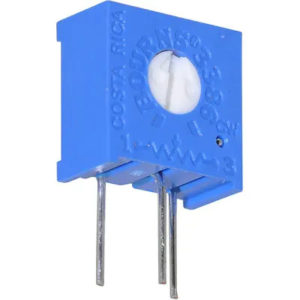
Trimpots or trimmer potentiometers are small potentiometers that are used for adjustment of resistance or voltage, calibration, and tuning in the circuit. These have a short lifespan and can be adjusted only a few hundred times. The trimpots are meant to be adjusted to fixed resistance ratio by rotating their knob by a screwdriver and then left with the made adjustment in the circuit. As these are set to fixed resistance ratio while calibration or tuning of a circuit, trimpots are also called preset. The trimpot or preset has the following IEC standard symbol:
The trimpots generally have carbon composition or ceramic composition resistive track. The trimpots come available for both through-hole and SMD mounting. These can have a top or side orientation of the knob for the adjustment of their resistance ratio. There are two types of presets:
1) Single Turn Trimpots – These are three-terminal presets with a single layer of resistive track. These are the most commonly used presets and have limited resolution and precision. Single Turn Trimpots generally comes in rotary design.
2) Multi-Turn Trimpots – Multi-Turn Presets have multiple turns of resistive track for higher resolution and precision. These trimpots can have 5 to 25 turns of which trimpots of 5, 12 and 25 turns are most common. These trimpots come available in worm-gear (rotary) or lead screw (linear) construction. The linear trimpots are commonly used in high power applications.
Digital potentiometers
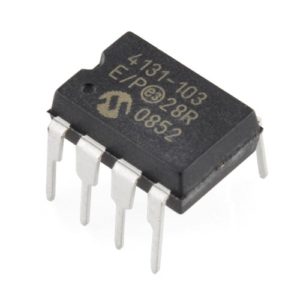
The digital potentiometers are integrated circuits that have an inbuilt resistor ladder for variation of resistance. Each resistor in the inbuilt ladder adds a step-change in resistance. The inbuilt wiper connects to different junctions of the resistor ladder via inbuilt switches for adjustment or calibration. Greater is the number of resistors in the ladder, higher is the resolution of the digital potentiometer. The wiper position and so the resistance ratio of the digital potentiometer is changed by passing digital signals to the IC or by passing appropriate digital signals over I2C or SPI interface. The resolution of digital potentiometers depends upon the number of bits controlling the pot. The 5-bit, 6-bit, 7-bit, 8-bit, 9-bit and 10-bit digital pots have a resolution of 32, 64, 128, 256, 512 and 1024 steps respectively. A digital potentiometer can have multiple potentiometers (up to 6 channels) within a single IC. The digital potentiometer has the following IEC standard symbol:
Many digital potentiometers come with inbuilt EEPROM to keep remember last wiper position. The digital pot ICs without EEPROM generally have wiper adjusted to the center position on power-up. These pots come available in a variety of resistance range of which 5k, 10k, 50k and 100k are most common. These potentiometers have tolerance from 20% to as low as 1%.
Most of the digital potentiometers come in 5V rating and are generally used in logic circuits or circuits involving microcontrollers or microprocessors. These pots are generally used in place of preset resistors or trimpots for high precision and resolution in digital circuits. There are hundreds of digital potentiometer ICs available like AD5110, MAX5386, DS1806, etc. Check out various digital pot ICs available at Mouser.
Rheostat
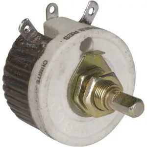
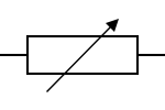
Rheostats are two-terminal variable resistors usually having wirewound construction. These are used for controlling current in the circuits. Some rheostat may have three terminals of which only two remain available for connections. One connection is made to one of the ends of the resistive track and other connection is made to the wiper. Rheostats used to be commonly used in power circuits to control current. However, nowadays mostly switching electronics is used in place of rheostats in power electronics applications. Like potentiometers, rheostats also come in a variety of constructions of which rotary, linear and 2-terminal preset resistors are most common. Like potentiometers, these can be single-turn or multi-turn types. There are also double gang and stacked rheostats. The rheostat has the following IEC standard symbol:
The preset resistor has the following IEC standard symbol:
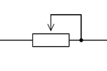
Most of the potentiometers and trimpots can be wired as a rheostat. A potentiometer or trimmer wired as rheostat has the following IEC standard symbol:
In the next article, we will discuss dependent resistors. Before that here are some Do-It-Yourself activities for you.
Activity 5
Look for various digital potentiometer ICs at various online market places like Mouser, Element14, Digi-Key, etc. Download their datasheets as well and check out various specifications like tolerance, linearity, resistance curve, number of channels, voltage rating etc.
Activity 6
Download random datasheets of linear and logarithmic potentiometers online and compare their resistance curve.
Filed Under: Featured Contributions





Questions related to this article?
👉Ask and discuss on Electro-Tech-Online.com and EDAboard.com forums.
Tell Us What You Think!!
You must be logged in to post a comment.