In the previous tutorials in this series, we have seen how to generate different chasing effects by blinking LEDs. So we were simply turning the LED ON and OFF.
In this tutorial, we shall vary the brightness (intensity) of LED. We shall use the PWM output of ATtiny85 to do this. So let’s see how to do this.
If you are not following this tutorial series from the beginning, you should go through the following two tutorials that explain and demonstrate how to work with ATtiny85 and step by step guide to build a hello world (LED blinking) application.
How to work with ATtiny85
LED blinking using ATtiny85
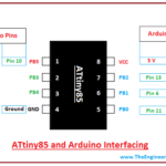
Circuit diagram
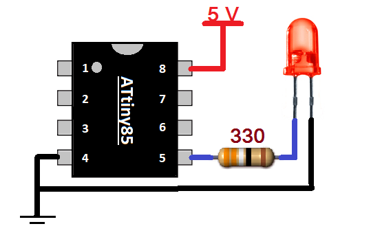
Circuit connections
The circuit diagram is very simple. Just one LED is connected to the PB0 pin (pin 5), that is also the PWM output pin. One 330 resistor is used to limit the current. A 5 V supply is connected to a Vcc pin (8).
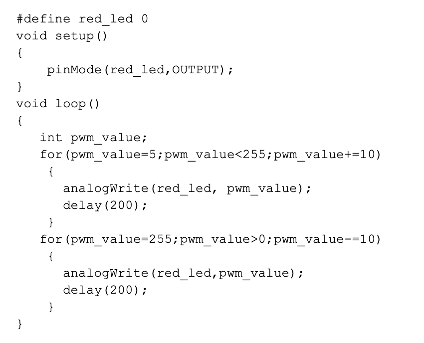
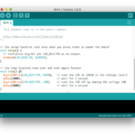
Program
The program is written in Arduino IDE software using C programming language. It is compiled, and a HEX file is created that is downloaded into the internal FLASH of ATtiny85.
Program logic
Program logic is straightforward. First, the PWM output is gradually increased from 5 to 255 (max width) in increments of 10. This PWM is given to LED, so its intensity will increase gradually. The LED intensity becomes from 0 (min) to the full (max) in 5 seconds. Then PWM output is decreased gradually from 255 to 0 in increments of 10. So LED intensity will decrease gradually from max to min again in 5 seconds. Once again PWM value starts increasing, and this cycle repeats continuously. So LED intensity continuously increases and decreases.
In the next tutorial, we shall learn to vary the brightness of LED using a potentiometer.
You may also like:


Filed Under: Tutorials

Questions related to this article?
👉Ask and discuss on EDAboard.com and Electro-Tech-Online.com forums.
Tell Us What You Think!!
You must be logged in to post a comment.