A single cell is not sufficient for some devices. To achieve the desired voltage, the cells are connected in series to add the voltage of cells. To achieve the desired capacity, the cells are connected in parallel to get high capacity by adding ampere-hour (Ah). This combination of cells is called a battery.
Sometimes battery packs are used in both configurations together to get the desired voltage and high capacity. This configuration is found in the laptop battery, which has four Li-ion cells of 3.6 V connected in series to get 14.4 V. Each cell has one another cell connected in parallel to get the double capacity of 6800mAh.
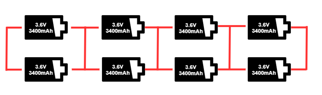
Laptop battery configuration.
The battery connected in the configuration should have the same voltage and capacity because the weaker cell causes an imbalance. In a series configuration, the battery is as strong as the weak link in the battery chain, so the higher-capacity cell cannot charge more than the weaker cell. The weaker cell also discharges and charge first, which also cause a problem like over-discharging and over-charge in the device.
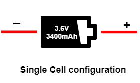
Single-cell configuration
The single-cell configuration is the simplest battery pack. This configuration is available in a wall clock, memory backup, and wristwatch. These all are low-power devices, so they use a 1.5 V alkaline battery. Mobile phones and tablets are also available in a single-cell configuration of a 3.6 V Li-ion battery. The image below shows the single-cell configuration of the Li-ion battery.
As we have seen, the nominal voltage of a single Li-ion cell is 3.6 V. A nickel-based battery has a nominal voltage of 1.2 V, and an alkaline battery has a nominal voltage of about 1.5 V. The other lithium-based battery has a voltage between 3.0 V to 3.9 V. Li-phosphate is 3.2 V, and Li-titanate is 2.4 V. Li-manganese and other lithium-based systems often use cell voltages of 3.7 V and higher.
Series configuration
The series configuration is used where the voltage of a single cell is not sufficient. The series configuration is achieved by connecting the positive of a cell to the negative of another cell, as shown in the image below. The four lithium-ion cells of 3.6 V connected in series will give you 14.4 V, and this configuration is called 4S because four cells are connected in series.
 The number of cells can be varied according to the voltage of a single cell. A Lead-acid battery has a nominal voltage of 2 V, so it requires six cells connected in series to achieve 12 V. The six alkaline batteries of voltage 1.5 V per cell connected in series will give you 9 V.
If the device needs an odd voltage, for example, 10 V, then three Li-ion batteries can be connected in series. But when the device needs 8.5 V from Li-ion, you need to know the specifications of your device. If it can handle 10 V, then it can be connected directly; otherwise, a buck or boost is used to achieve 8.5 V.
If one cell in a series is faulty, cell matching is a challenge in an aging pack at the time of cell replacement. The new cell has a higher capacity than the others, which causes imbalance. That’s why battery packs are commonly replaced in units.
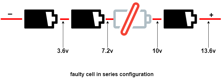
BMS (Battery Management Systems) or its controller can determine the faulty battery by measuring the voltage at every point of the battery as shown below in the image. The one cell is faulty, which is giving 2.8 V instead of 3.6 V. Due to this, the battery voltage collapses, and the device will shut off sooner with a low-battery message. You can repair your battery pack by replacing this cell.
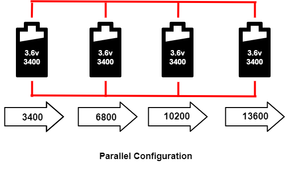
 Parallel configuration
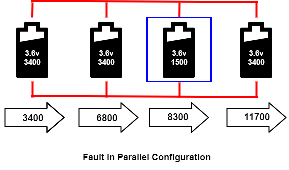
The cells are connected in parallel to fulfill higher current capacity requirements if the device needs a higher current, but there is not enough space available for the battery. That device can use the parallel configuration to fit high-current capability in a small space. The four-cell configuration in parallel is called P4, and the three cells connected in a parallel configuration are called P3. The image below shows a P4 configuration. The voltage in the pack remains the same, but the current capacity(Ah) is increased.
 The cell that develops high resistance or opens is less critical in a parallel circuit than in a series configuration, but the failing cell will reduce the total current capacity. On the other hand, an electrical short is more serious as the faulty cell drains energy from the other cells, and causes a fire. The short occurs through reverse polarization or dendrite growth. The large cell includes a fuse to disconnect the failing cell when it shorts. In the image below, the third cell in the blue box failed, and the capacity was reduced to 1500 mAh. It does not affect the voltage, but it reduces the total capacity.
 Series – parallel configuration
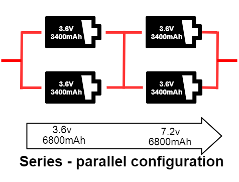
In this configuration, the cells are connected in both series and parallel. The series-parallel configuration can give the desired voltage and capacity in the smallest possible size. You can see two 3.6 V 3400mAh cells connected in parallel in the image below, which doubles the current capacity from 3400 mAh to 6800 mAh. Because these parallel packs are connected in series, the voltage also doubles from 3.6 V to 7.2 V. The total power of this pack is now 48.96 Wh. This configuration is called 2SP2. If the configuration consists of eight cells with the configuration of 4SP2, two cells are in parallel, and four packs of this parallel combination are connected in series. The total power produced by this pack is 97.92 Wh.
 Protection in batteries
The IEC 62133 harmonized the safety requirements for nickel and lithium-based batteries and cells for portable applications. The Li-ion batteries are the most dangerous battery in their category because the battery chemistry has explosive material. Battery protection is required to prevent any damage due to high current discharge, overcharge, temperature rise, etc. The protection can be built into the structure of the battery or the external protection circuit can be used to disconnect the battery.
Built-in protection in batteries
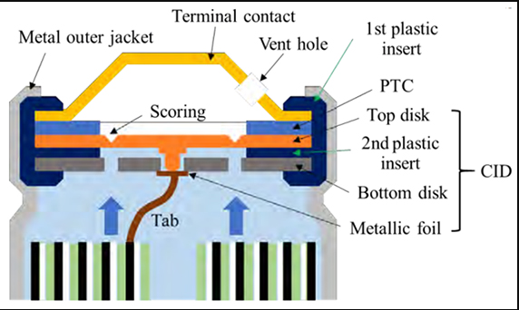
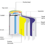
Some batteries come with safety features within the battery structure. The image below illustrates the safety feature of the 18650 Li-ion cells. The PTC (positive thermal coefficient) is the resistance that is very low during normal temperature. But when the temperature goes above critical condition, its resistance rises to reduce the current flow. PTC comes under normal resistance when the temperature goes below the critical range.
The CID (current interrupt device) is a fuse-type device that permanently cuts off the circuit when the range of cell pressure, temperature, or voltage exceeds its limits. If the internal pressure increases by about 1,000 kPa, the top disc disconnects from the metallic foil and disconnects the current flow. There is a vent on top to release the gas and it can be closed again.
Built-in protection.FE
Protection circuit in batteries
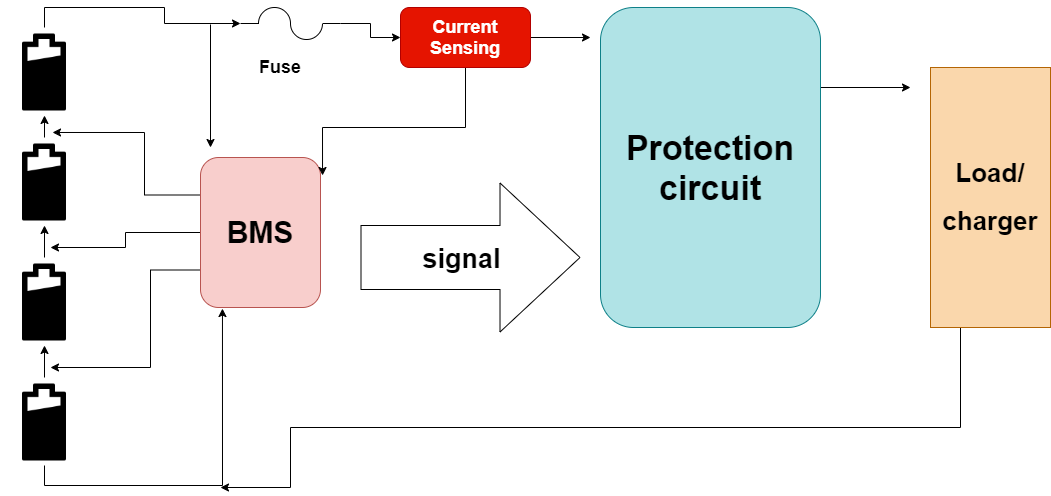
Some 18650 Li-ion batteries come with a protection circuit. The basic function of the protection circuit is to protect batteries from over-voltage, under-voltage, over-current, and over and under-temperature. This is a part of BMS. The BMS monitors the state of the batteries for safer operations and sends the signal to the protection circuit if there is any fault in the batteries. When the protection circuit is connected at the battery’s positive terminal, it is called high-side protection. When it is connected to the negative side of the battery, then it is called negative-side protection.
The protection circuit block diagram is given below. This is a High side protection circuit. The battery configuration is S4 (four in series), and a fuse is connected to the positive side of the battery to shut off the battery when the current exceeds the limits. There is BMS Monitoring every cell voltage for balancing and fault detection. The current sensing unit will sense the charge and discharge the current it sends to BMS. If any reading of voltage or current exceeds the limits, then BMS sends the signal to the protection circuit that shuts off the cell with a charger or load.
Protection circuit in batteries.
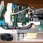
There are some pre-made circuits available in the market which are fixed for your voltage or current requirements. You simply have to know the current and voltage specifications of battery protection modules, or you can also build your own with MOSFETs and BMS available in the market.
References
- https://batteryuniversity.com
- https://www.plainviewisd.org/
- https://www.power-sonic.com/blog/how-to-connect-batteries-in-series-and-parallel/
- https://www.epectec.com/batteries/battery-configuration.html
- https://robu.in/series-and-parallel-configuration-of-lithium-battery/
- https://batteryuniversity.com/learn/article/safety_circuits_for_modern_batteries
You may also like:


Filed Under: Battery Management, Tutorials

Questions related to this article?
👉Ask and discuss on EDAboard.com and Electro-Tech-Online.com forums.
Tell Us What You Think!!
You must be logged in to post a comment.