The aim of the project is to make a portable LED display from SMD LEDs and to display the custom programmed patterns at our command. The core application of the project is to act as a portable display for event organisers or exhibitionists or consultants to make announcements at their mobile facilities. This can also be used as a novelty item in a showcase.

Fig. 1: Image showing PCB Soldering for Bluetooth Controlled LED Display
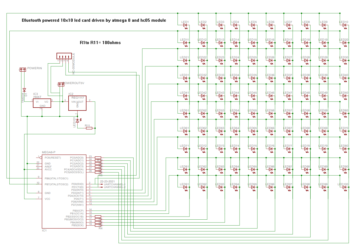
Multiplexed LED Display
Atmega8 Controller
This controller is run by an 8 Mhz internal RC clock source. The control wires are connected to the controller port pins. All the cathodes of the display were directly connected to the MCU while the anode pins were connected through a current limiting 100ohms resister. The Uart communication peripheral of the MCU is used to establish the communication between MCU and Bluetooth module. This Uart peripheral is set at 9600bps baud rate.
Hc-05 Bluetooth Module
The Bluetooth module used is configured with a new name and its baud value is set to 9600bps
Power Rail Circuit
The Bluetooth module used requires a steady 5v source for proper operation and its Uart logic is based on 3.3v. Therefore the MCU is given a 3.3v potential to run so as to match the logic level and decrease the LED brightness. Hence a 7805 regulator in series with 1117s 3.3v LDO is used to provide necessary voltage levels. Also a protection diode is used in series with power supply input.

Fig. 2: Image showing Power Relay Circuit on PCB
Circuit
The Circuit is attached in the Circuit Diagram Tab. All the resistors used are 100 Ohms.
Code
Hardware Used
Software Used
Project Source Code
###
#include<avr/io.h> #include<util/delay.h> void active(int,int,float); void uartinit(unsigned int); void uarttrans (unsigned char); unsigned char uartrec (void); int pat1(void); int pat2(void); int pat3(void); int pat4(void); int pat5(void); int main(void) { char c; uartinit(51); //sets baud to 9600bps DDRB = 0b11111111;//6-pins DDRC = 0b111111;//6-pins DDRD = 0b11111100;//8-pins while(1) { c = uartrec(); switch(c) { case 'A':pat1(); break; case 'B':pat2(); break; case 'C':pat3(); break; case 'D':pat4(); break; case 'E':pat5(); break; } uarttrans(c); } return 0; } void active(int x,int y,float f) { switch(y) { case 9: PORTB |= 1<<PORTB6; break; case 8: PORTB |= 1<<PORTB7; break; case 7: PORTD |= 1<<PORTD2; break; case 6: PORTD |= 1<<PORTD3; break; case 5: PORTD |= 1<<PORTD4; break; case 4: PORTD |= 1<<PORTD5; break; case 3: PORTD |= 1<<PORTD6; break; case 2: PORTD |= 1<<PORTD7; break; case 1: PORTB |= 1<<PORTB0; break; case 0: PORTB |= 1<<PORTB1; break; } switch(x) { case 0: PORTB &= ~(1<<PORTB2); break; case 1: PORTB &= ~(1<<PORTB3); break; case 2: PORTB &= ~(1<<PORTB4); break; case 3: PORTB &= ~(1<<PORTB5); break; case 4: PORTC &= ~(1<<PORTC0); break; case 5: PORTC &= ~(1<<PORTC1); break; case 6: PORTC &= ~(1<<PORTC2); break; case 7: PORTC &= ~(1<<PORTC3); break; case 8: PORTC &= ~(1<<PORTC4); break; case 9: PORTC &= ~(1<<PORTC5); break; } _delay_ms(f); PORTC = ~0b000000; //deactive logic PORTB = 0b00111100; PORTD = 0b00000000; } void uartinit(unsigned int ubbr) { UBRRL = ubbr; UBRRH = ubbr>>8; UCSRC = (1<<URSEL) |(1<<UCSZ0)|(1<<UCSZ1); UCSRB = (1<<RXEN)|(1<<TXEN); } void uarttrans (unsigned char ch) { while (!( UCSRA & (1<<UDRE))) { } UDR = ch; } unsigned char uartrec (void) { while(!(UCSRA) & (1<<RXC)) { } return UDR; } int pat1(void) { int i; for(i=0;i<10;i++) { active(i,i,10); } for(i=0;i<10;i++) { active((i),(9-i),10); } return 0; } int pat2(void) { int i,j; { for(i=0;i<10;i++) for(j=0;j<10;j++) { active(i,j,1.06); } } { for(i=0;i<10;i++) for(j=0;j<10;j++) { active(j,i,1.06); } } return 0; } int pat3(void) { int i,j; { for(i=0;i<10;i++) for(j=0;j<10;j++) { active(i,9-j,0.1); } } { for(i=0;i<10;i++) for(j=0;j<10;j++) { active(9-j,i,0.1); } } return 0; } int pat4(void) { int k; int p[] = { 0 , 0 , 0 , 0 , 0 , 0 , 0 , 1 , 1 , 1 , 2 , 1 , 1 , 1 , 1 , 2 , 2 , 2 , 2 , 2 , 3 , 3 , 3 , 3 , 3 , 4 , 4 , 4 , 5 , 5 , 5 , 5 , 5 , 6 , 7 , 7 , 7 , 8 , 8 , 8 , 8 , 9 , 9 , 9 , 9 , 9 , 9 }; //i m dls xco int q[] = { 6 , 0 , 1 , 2 , 3 , 4 , 9 , 6 , 0 , 4 , 6 , 6 , 7 , 8 , 9 , 1 , 2 , 3 , 6 , 9 , 0 , 1 , 2 , 3 , 4 , 8 , 9 , 0 , 0 , 6 , 6 , 7 , 8 , 9 , 0 , 3 , 8 , 0 , 2 , 4 , 9 , 1 , 4 , 6 , 6 , 7 , 8 }; //i m dls yco for(k=0;k<51;k++) active(p[k],q[k],.1); return 0; } int pat5(void) { int k,l,t=1000; int p1[] = { 1 , 1 , 1 , 1 , 1 , 1 , 2 , 3 , 4 , 5 , 6 , 7 , 8 , 8 , 8 , 8 , 8 , 8 , 9 };//v-xco-18 int q1[] = { 3 , 4 , 5 , 6 , 7 , 8 , 2 , 1 , 0 , 0 , 1 , 2 , 3 , 4 , 5 , 6 , 7 , 8 , 0 };//v-yco int p2[] = { 1 , 1 , 1 , 1 , 1 , 1 , 1 , 1 , 2 , 3 , 4 , 5 , 6 , 7 , 8 , 8 , 8 , 8 , 8 , 8 , 8 , 8 , 9 };//n-xco-22 int q2[] = { 1 , 2 , 3 , 4 , 5 , 6 , 7 , 8 , 9 , 9 , 9 , 9 , 9 , 9 , 8 , 7 , 6 , 5 , 4 , 3 , 2 , 1 , 0 };//n-yco int p3[] = { 2 , 2 , 2 , 2 , 2 , 2 , 2 , 2 , 2 , 2 , 3 , 3 , 3 , 4 , 4 , 4 , 5 , 5 , 5 , 6 , 6 , 6 , 7 , 7 , 7 , 7 , 7 , 9 };//r-xco-27 int q3[] = { 0 , 1 , 2 , 3 , 4 , 5 , 6 , 7 , 8 , 9 , 4 , 5 , 9 , 3 , 5 , 9 , 2 , 5 , 9 , 1 , 5 , 9 , 0 , 5 , 6 , 7 , 8 , 0 };//r-yco for(l=0;l<t;l++) for(k=0;k<18;k++) active(p1[k],q1[k],0);//v for(l=0;l<t;l++) for(k=0;k<23;k++) active(p2[k],q2[k],0);//n for(l=0;l<t;l++) for(k=0;k<28;k++) active(p3[k],q3[k],0);//r return 0; }###
Circuit Diagrams
Project Video
Filed Under: Electronic Projects
Filed Under: Electronic Projects

Questions related to this article?
👉Ask and discuss on EDAboard.com and Electro-Tech-Online.com forums.
Tell Us What You Think!!
You must be logged in to post a comment.