Engineers Garage

  • Electronics Projects and Tutorials
    • Electronic Projects
      • Arduino Projects
      • AVR
      • Raspberry pi
      • ESP8266
      • BeagleBone
      • 8051 Microcontroller
      • ARM
      • PIC Microcontroller
      • STM32
    • Tutorials
      • Audio Electronics
      • Battery Management
      • Brainwave
      • Electric Vehicles
      • EMI/EMC/RFI
      • Hardware Filters
      • IoT tutorials
      • Power Tutorials
      • Python
      • Sensors
      • USB
      • VHDL
    • Circuit Design
    • Project Videos
    • Components
  • Articles
    • Tech Articles
    • Insight
    • Invention Stories
    • How to
    • What Is
  • News
    • Electronic Product News
    • Business News
    • Company/Start-up News
    • DIY Reviews
    • Guest Post
  • Forums
    • EDABoard.com
    • Electro-Tech-Online
    • EG Forum Archive
  • DigiKey Store
    • Cables, Wires
    • Connectors, Interconnect
    • Discrete
    • Electromechanical
    • Embedded Computers
    • Enclosures, Hardware, Office
    • Integrated Circuits (ICs)
    • Isolators
    • LED/Optoelectronics
    • Passive
    • Power, Circuit Protection
    • Programmers
    • RF, Wireless
    • Semiconductors
    • Sensors, Transducers
    • Test Products
    • Tools
  • Learn
    • eBooks/Tech Tips
    • Design Guides
    • Learning Center
    • Tech Toolboxes
    • Webinars & Digital Events
  • Resources
    • Digital Issues
    • EE Training Days
    • LEAP Awards
    • Podcasts
    • Webinars / Digital Events
    • White Papers
    • Engineering Diversity & Inclusion
    • DesignFast
  • Guest Post Guidelines
  • Advertise
  • Subscribe

Circuit Design: Pulse Amplitude Modulation

By Ashutosh Bhatt September 30, 2013


There are different kinds of modulation technique based on varying the properties of a pulse train. The Pulse Width Modulation (PWM) varies the width of individual pulses according to the amplitude of the modulating signal. The Pulse Position Modulation (PPM) varies the position of individual pulses from their mean position according to the amplitude of the modulating signal. The PWM is a kind of modulation technique indented for power efficiency, but the power required to transmit individual pulses varies significantly. In PPM modulation technique the power required for transmitting individual pulses are constant, but synchronization of transmitter and receiver are required. There is a simple pulse modulation technique called Pulse Amplitude Modulation (PAM) which is proved to be more power efficient than the PWM and consumes constant power for individual pulses.

In PAM the amplitude of the individual pulses are varied according to the amplitude of the modulating signals. The PAM modulator and demodulator circuits simple compared to other kind of modulation and demodulation techniques. There are two kinds of PAM one in which the pulses have the same polarity and the other in which the pulses can have both positive and negative polarity according to the amplitude of the modulating signal.

This article demonstrate how to generate a single polarity PAM wave corresponding to a modulating sine wave with the help of simplest possible circuitry.

DESCRIPTION:

Unlike the AM modulation which varies the amplitude of the carrier signal in both the sides from the mean position, the PAM modulation varies the amplitude of the pulses only at a single side. Simply the top of the pulses are modulated corresponding to the message signal. In this project the PAM is generated from a pure sine wave modulating signal and a square wave generator which produce the carrier pulses and a PAM modulator circuit. The block diagram of the PAM modulation is given in the following:   

Block Diagram of Pulse Amplitude Modulation (PAM )

Fig. 1: Block Diagram of Pulse Amplitude Modulation (PAM )

{     1)  Variable frequency sine wave generator

A sine wave generator circuit is used in this project which is based on the Wien Bridge Oscillator (WBO) circuit. The Wien Bridge oscillator circuit can produce distortion less sinusoidal sweep at its output. The circuit is designed in such a way that both the amplitude and frequency of the oscillator can be adjusted using potentiometers.

The circuit diagram of the variable frequency sine wave oscillator is shown in the following:

Circuit Diagram of Variable Frequency Sine Wave Oscillator

Fig. 2: Circuit Diagram of  Variable Frequency Sine Wave Oscillator

Variable Frequency Sine Wave Oscillator Circuit on Breadboard

Fig. 3: Variable Frequency Sine Wave Oscillator Circuit on Breadboard

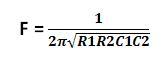
The frequency of the above circuit can be varied by simply varying the potentiometer R2 and the amplitude of the wave form can be adjusted by varying the potentiometer R. The frequency of the sine wave generated by the above circuit depends on the components R1, R2, C1 and C2 and the equation for the frequency is given below:

Formula for frequency

For the ease of adjusting the amplitude of the wave to obtain proper sinusoidal sweep, a coarse and fine adjustment has been implemented using potentiometers. A low value (1K) potentiometer is connected in series with the high value (100K) potentiometer so that the coarse adjustment can be done with the high value resistor and the fine adjustment with the low value resistor.

The snapshot of the waveform formed at the CRO screen using the WBO circuit is shown in the following image:

Sine Wave Waveform Displayed on CRO

Fig. 4: Sine Wave Waveform Displayed on CRO 

{     2) SQUARE WAVE GENERATOR

The square wave is generated in this project using an op-amp based astable circuit. The op-amp based astable circuit is used to generate the square wave due to the less number of components required and less complex circuit. The ON-time and the OFF-time of the pulses can be made identical and the frequency can be easily adjusted without changing them. However in this project the circuit is designed to be producing a constant frequency.  The astable multivibrator circuit using op-amp 741 is given below.

Circuit Daigram of Square Wave Generator

Fig. 5: Circuit Diagram of Square Wave Generator

The time period of the pulses generated by the above circuit depends upon the values of the resistor R and the capacitor C. The following equation gives the approximate time period of the pulses generated by the op-amp astable multivibrator circuit.

T = 2.2 * R*C

 PAM Modulator

Since the value of the resistor is selected as 1K and the capacitor is selected as 0.01uF, the time period of the pulse is:

T = 2.2 * 10^3 * 0.01 * 10^-6  = 2.2 * 10 ^ -5 seconds.

Since frequency F = 1 / T, the frequency of the pulses generated by the above circuit is calculated as

F = 1 / 2.2 * 10 ^ -5 = 45 KHz.

Square Wave Generator Circuit on Breadboard

Fig. 6: Square Wave Generator  Circuit on Breadboard

       3)  PAM MODULATOR

The PAM modulator circuit in this project has to modify the amplitude of the pulses having a frequency of 45 KHz with the modulating sine wave of frequency 1 KHz. The modulator here is realized using a simple FET and a couple of resistors.  The FET used here is BFW10 which is an N-channel FET and since it is a unipolar device it is suitable for applications in which the signals having both positive and negative polarities are used.

PAM Modulator Circuit Diagram

Fig. 7: PAM Modulator Circuit Diagram

PAM Modulator Circuit on Breadboard

Fig. 8: PAM Modulator Circuit on Breadboard

The resistors are simply used as current limiters where the 10K resistor is used to limit the current flowing into the base of the FET and the 1K resistor is used to limit the current flowing through the N-channel. The PAM signal is obtained across the 1K resistor and the ground.

The image of the CRO screen displaying a single polarity PAM wave is given below:

CRO Screen Displaying Single Polarity PAM Wave

Fig. 9: CRO Screen Displaying Single Polarity PAM Wave

The complete circuit diagram is given below:

PAM Circuit

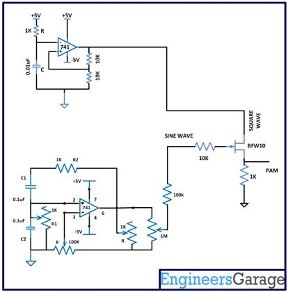
Fig. 10: Circuit Diagram of PAM Modulator

The image of the complete circuit diagram wired in the breadboard is given below:

Circuit Diagram of PAM Modulator

Fig. 11: Pulse Amplitude Modulation Circuit on Breadboard  


Filed Under: Circuit Design


Next Article

← Previous Article
Next Article →

Questions related to this article?
👉Ask and discuss on Electro-Tech-Online.com and EDAboard.com forums.


Tell Us What You Think!! Cancel reply

You must be logged in to post a comment.

EE TECH TOOLBOX

“ee
Tech Toolbox: Internet of Things
Explore practical strategies for minimizing attack surfaces, managing memory efficiently, and securing firmware. Download now to ensure your IoT implementations remain secure, efficient, and future-ready.

EE Learning Center

EE Learning Center
“engineers
EXPAND YOUR KNOWLEDGE AND STAY CONNECTED
Get the latest info on technologies, tools and strategies for EE professionals.

HAVE A QUESTION?

Have a technical question about an article or other engineering questions? Check out our engineering forums EDABoard.com and Electro-Tech-Online.com where you can get those questions asked and answered by your peers!


RSS EDABOARD.com Discussions

  • RF-DC rectifier impedance matching
  • 12VAC to 12VDC 5A on 250ft 12AWG
  • Precision CAD Drafting Services for Architectural & Engineering Projects
  • SPI speed pic18f66j15
  • I/O constraint for Hold check

RSS Electro-Tech-Online.com Discussions

  • LED circuit for 1/6 scale diorama
  • stud mount Schottky diodes
  • Hi Guys
  • using a RTC in SF basic
  • Can I use this charger in every country?

Featured – Designing of Audio Amplifiers part 9 series

  • Basics of Audio Amplifier – 1/9
  • Designing 250 Milli Watt Audio Power Amplifier – 2/9
  • Designing 1 Watt Audio Power Amplifier – 3/9
  • Designing a Bass Boost Amplifier – 4/9
  • Designing a 6 Watt Car Audio Amplifier – 5/9
  • Design a low power amplifier for headphones- 6/9

Recent Articles

  • Fischer connector system adds ratchet locking system designed for 300g shock resistance
  • Littelfuse introduces tactile switch with enhanced bracket peg design for mounting strength
  • Infineon releases GaN switch with monolithic bidirectional design
  • Sienna Semiconductor data converters feature sample rates from 20 to 250 Msps
  • Delta’s 5,500 W power supplies achieve 97.5% energy efficiency for AI servers

EE ENGINEERING TRAINING DAYS

engineering

Submit a Guest Post

submit a guest post
Engineers Garage
  • Analog IC TIps
  • Connector Tips
  • Battery Power Tips
  • DesignFast
  • EDABoard Forums
  • EE World Online
  • Electro-Tech-Online Forums
  • EV Engineering
  • Microcontroller Tips
  • Power Electronic Tips
  • Sensor Tips
  • Test and Measurement Tips
  • 5G Technology World
  • Subscribe to our newsletter
  • About Us
  • Contact Us
  • Advertise

Copyright © 2025 WTWH Media LLC. All Rights Reserved. The material on this site may not be reproduced, distributed, transmitted, cached or otherwise used, except with the prior written permission of WTWH Media
Privacy Policy

Search Engineers Garage

  • Electronics Projects and Tutorials
    • Electronic Projects
      • Arduino Projects
      • AVR
      • Raspberry pi
      • ESP8266
      • BeagleBone
      • 8051 Microcontroller
      • ARM
      • PIC Microcontroller
      • STM32
    • Tutorials
      • Audio Electronics
      • Battery Management
      • Brainwave
      • Electric Vehicles
      • EMI/EMC/RFI
      • Hardware Filters
      • IoT tutorials
      • Power Tutorials
      • Python
      • Sensors
      • USB
      • VHDL
    • Circuit Design
    • Project Videos
    • Components
  • Articles
    • Tech Articles
    • Insight
    • Invention Stories
    • How to
    • What Is
  • News
    • Electronic Product News
    • Business News
    • Company/Start-up News
    • DIY Reviews
    • Guest Post
  • Forums
    • EDABoard.com
    • Electro-Tech-Online
    • EG Forum Archive
  • DigiKey Store
    • Cables, Wires
    • Connectors, Interconnect
    • Discrete
    • Electromechanical
    • Embedded Computers
    • Enclosures, Hardware, Office
    • Integrated Circuits (ICs)
    • Isolators
    • LED/Optoelectronics
    • Passive
    • Power, Circuit Protection
    • Programmers
    • RF, Wireless
    • Semiconductors
    • Sensors, Transducers
    • Test Products
    • Tools
  • Learn
    • eBooks/Tech Tips
    • Design Guides
    • Learning Center
    • Tech Toolboxes
    • Webinars & Digital Events
  • Resources
    • Digital Issues
    • EE Training Days
    • LEAP Awards
    • Podcasts
    • Webinars / Digital Events
    • White Papers
    • Engineering Diversity & Inclusion
    • DesignFast
  • Guest Post Guidelines
  • Advertise
  • Subscribe