Controlling Led brightness using Meditation and attention level
SUMMARY
After talking about the theoretical concept of brain waves, it’s time to check out some real-time applications. Here, we are going to discuss the efficiency, flexibility and various features of what we have done till now. Presently, I am thinking of changing something depending on my attention and meditation level, say the brightness of a small LED. We will be controlling the brightness of an LED using the attention and meditation levels of our Brain at any particular time. We will be using Arduino UNO and mindflex sensor which we have chosen to read the brain wave and an LED to show the results.
DESCRIPTION
We are changing the brightness of the LED which can be easily controlled using PWM technique.
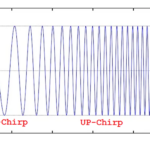
Quick Note: PWM is a technique to control analog devices by digital outputs. By digital outputs, we are creating a square wave of ON and OFF patterns. This ON and OFF pattern is used to create analog voltage ranging between Low Voltage and High Voltage and we can vary the voltage by changing the duration of ON time with respect to OFF time.
If we pass this ON OFF pattern to the LED at high speed, apparently an analog voltage is received and its brightness changes accordingly.
First, let us control the LED brightness using the attention level.
So, now to control an LED’s brightness, we will measure the attention level from e meters of the TGAM1 chip. Please note that this chip gives us the attention level on a scale of 0 – 100. It is also interesting to know that the chip transmits the Meditation signals only when the sensor is accurately connected to the Brain and the sensor module is getting 100% signal strength. The signal strength ranges from 0 – 200.

Fig. 1: Image Showing Brightness of an LED Being Controlled by Meditation Level Using Brainwave Sensor
Dramatically, when the signal strength is 100% then the sensor sends 0 value and when the sensor sends 200 this means there is no connection of the metal sensor to our brain. So, after confirming that our signal strength is 100% and our sensor is sending 0 serially for signal strength we can perform this experiment.
Now as we know that the PWM has a duty cycle which determines the analog level. The duty cycle is basically the on time divided by total time period. To change the brightness of the LED on the basis of attention level, we will change the duty cycle of PWM.
As we are getting the meditation value from the sensor on a scale of 0 -100, we will make the value of duty cycle equals to meditation value subtracted from 100. For example, if the meditation value from the sensor is 40 then the duty cycle is 100–40=60.
Fig. 2: Image showing brightness of an LED being controlled by Meditation Level using Brainwave Sensor
This will make the LED brightness parallel to the meditation level. You can check the code and the video for this experiment. After the meditation level, we will do the same with the attention level. Just to remind again, please check that the signal strength is coming 100% and with 0 value.
Fig. 3: Image showing brightness of an LED being controlled by Meditation Level using Brainwave Sensor
We again need to take the attention values from the sensor and change the PWM duty cycle with respect to the attention values. Again, make the value of duty cycle equals to the attention value subtracted from 100. For ex, if the meditation value from the sensor is 40 than the duty cycle is 100 – 40 = 60.
Check out the software section to see how PWM is implemented in the code.
And we are also done with the brightness control using attention values. Check out the code and video to perform the experiment yourself.

Fig. 4: Block Diagram of MindFlex Brainwave Sensor based LED Brightness Controller
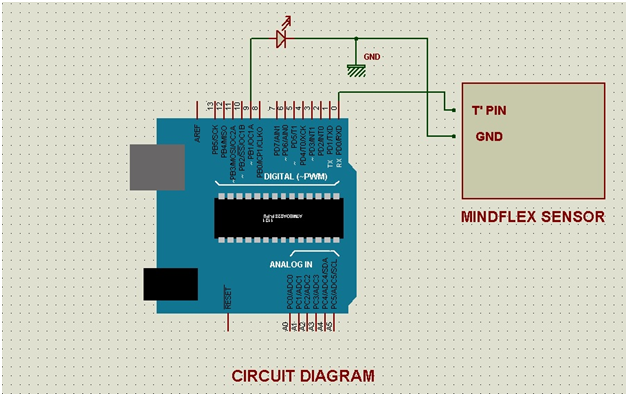
Hardware: Please find the attached circuit diagram of the connections we need to do. We have taken a pin from T pin of the mindflex sensor and connected that pin to the Rx pin of our Arduino UNO. Also, we have shorted the ground of both the Sensor and UNO by a wire. Please take special care while soldering anything to the Mindflex sensor as pins are very close to each other.
Softwares: Let us come to the software part. We have been receiving the E meter values from the sensor to our arduino via T pin. Once we have received the value at any particular point, we just need to convert that value level to the brightness of LED. As discussed previously, we will use PWM techniques. PWM in arduino is done by analogWrite: For ex
AnalogWrite(13,240);
AnalogWrite in arduino is used to write PWM wave to a pin. In above example, first parameter is PIN Number and second is PIN value. So, we are writing 240 to pin 13. Now we can calculate the analog voltage at the value 240 easily. Total voltage range is 0v – 5v and value range is 0- 255.
This means 240 = (5/255)*240 = ~4.70V.
Now the values we get from e meters are in range 0 – 100.
So let’s say we get evalue = 70.
We will multiply the e value by 2.55 to make it in the range of 0-255.
So it will be analogWrite (pin,evalue*2.55) in a loop.
Few points to Note:
The sensor usually gives the strength from 60 – 80% due to its orientation and the spot where we place it. Try to keep the metal sensor exactly above your left eye. I have also applied salt water at my forehead for better connectivity to the sensor. If you do not find it 100%, then it is normal. In the upcoming articles, I will explain how we can control various objects without signal attention and meditation values.
The signal strength also disrupts about how we solder the wire to the T pin. Try to shield this wire and also make sure that the references probes are correctly connected. If you have any wire connected to the EEG pin of the sensor, please disconnect that wire as that will create noise in the sensor values.
Try this experiment and let me know if you have any problem. Stay tuned for more experiments based on Brain Waves related to controlling a motor.
You may also like:


Project Source Code
###
//Program to#include// Set up the brain parser, pass it the hardware serial object you want to listen on.Brain brain(Serial);//char a[400];String a,a1;int v = 0;int z=0,output;uint32_t num=0;uint32_t num1=0;void setup() {// Start the hardware serial.Serial.begin(9600);pinMode(9, OUTPUT);}void loop() {// Expect packets about once per second.// The .readCSV() function returns a string (well, char*) listing the most recent brain data, in the following format:// "signal strength, attention, meditation, delta, theta, low alpha, high alpha, low beta, high beta, low gamma, high gamma"if (brain.update()) {// Serial.println(brain.readErrors());// Serial.println(brain.readCSV());//sprintf(a, "%c",brain.readCSV());a = brain.readCSV();v = a.indexOf(',');v = a.indexOf(',',v+1);v = a.indexOf(',',v+1);v = a.indexOf(',',v+1);z = a.indexOf(',',v+1);a1 = a.substring(v+1,z);num = a1.toInt();v = a.indexOf(',',z+1);a = a.substring(z+1,v);num1 = a.toInt();//Serial.println(num);Serial.println(num1);analogWrite(9,output)//brain.readCSV().toCharArray(a,200);}}###
Circuit Diagrams
Project Video
Filed Under: Brainwave, Tech Articles, Tutorials
Filed Under: Brainwave, Tech Articles, Tutorials

Questions related to this article?
👉Ask and discuss on Electro-Tech-Online.com and EDAboard.com forums.
Tell Us What You Think!!
You must be logged in to post a comment.