Discussing the use of sensor, its main aim is to sense the brainwave or electrical signals near the area of our brain, filter them by removing noise and fluctuations, and then convert the respective signals in their digital values. The data of the power FFT values of 8 different types of Brainwave is sent serially in our sensor.
Now, we will take a look at the working of the sensor, which will explain the various blocks inside the sensor that enables it to convert our brain signals into digital values.
Working
When the signals are measured directly from our brain, the amplitude is in the range of micro voltages. These signals also contain the noise from environment, and are also affected by the stray fields present in the area. We as a body also emit many other waves, which get mixed with the sensor and form a part of the results. In order to get a clear signal from the received waves we need to use many filters, amplifiers, and a circuit to enhance the results.
Following are the steps that we need to follow so as to imitate the sensor and produce similar results.
Steps
1. Amplifier
2. High Pass Filter
3. Amplifier
4. Low pass Filter
5. Analog to Digital Convertor
6. FFT
7. Coding
Let’s have a look at these steps one by one.
AMPLIFIER
Instrumentation amplifier is used after the raw signals and carries many benefits as compared to the simple differential amplifier. In differential amplifier, the input impedance does not approach infinity. Also, the input resistance on the inverting input is relatively low. Due to the unmatched input impedance, there is a large difference when compared to the non inverting input.
Though we can increase the input impedance by making changes in the feedback resistance but then to achieve a gain of 10, we would require 10M ohm resistance, if feedback resistance is made 1M ohm. Also, my personal experience is that large resistors are very noisy and it is difficult to match them. Moreover, large resistance sometimes causes stray capacitance.
In case of instrumentation amplifier, we can get infinite input impedance as well as high gain both at the same time. The result is a circuit with high gain along with CMRR and input impedance. Instrumentation amplifiers are specialized in amplifying weak and noisy signals and are very apt in our case where the signal is too noisy and is of low amplitude.
So, the first step is to apply an instrumentation amplifier with a gain of approx 100. Hence, we can get a signal in order of milli voltages which can be further read by our circuit and controller.
HIGHPASS FILTER
Now after we have got the amplified output, we need to start filtering the signal and keep it within the desired frequency. First we will filter all the low frequencies by using the High pass filter. We can use a simple Passive RC High pass filter, but that will lower the signal strength to much extent which is not desirable in our system. So, we will use active high pass filter after the amplified signal.
We will filter all the frequencies below 0.1 Hz. Our range of Brainwave signal is 0.1Hz to 50Hz. The lowest brain wave signals are delta wave with frequency range 0.1 to 3Hz. The cut off frequency in a high pass filter is measured by the following formula- :
Cut off Frequency = 1/(2*pie*R*C) in Hz
So, we will set the values of RC such that the cut off frequency is 0.1Hz. In this way, we have attenuated the frequencies below 0.1Hz. We are now left with frequencies ranging from 0.1Hz to infinite.
An additional benefit of active high pass filter over passive is that we can get amplification and gain control.
AMPLIFIER
Again we will use amplifier to amplify our signals. Here we can use differential amplifier too as our signal is not as small and the required gain is not in order of 100. A gain of 5 – 10 is sufficient in this step. The gain can be achieved by proper resistance values and their ratios.
Our main task is to act as repeater and give more strength to the signal so as to pursue further processing.
LOW PASS FILTER
Now after we have got the amplified output, we need to start filtering the signal again and limit the signal within our desired frequency of 0.1Hz to 50 Hz. We have already limited it to 0.1Hz. We can use a simple Passive RC Low pass filter, but again that will lower the signal strength to much extent which is not desirable in our system. So we will use active low pass filter after the amplified signal..
We will filter all the frequencies after 50 Hz this time. Our range of Brainwave signal is 0.1Hz to 50Hz .The highest brain wave signals are gamma wave with frequency range 38Hz to 45Hz. The cut off frequency in a low pass filter is measured by the following formula. This is same as that of high pass filter.
Cut off Frequency = 1/(2*pie*R*C) in Hz
So, we will set the values of RC such that the cut off frequency is 50Hz. In this way we have attenuated the frequencies after 50Hz. We are now left with frequencies ranging from 0.1Hz to 50Hz. We have removed the noise and stray signals except this frequency range. Though there will be few signals in this freq range which are not actual brain waves.
REFERENCE
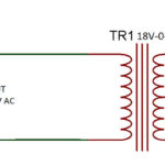
We have attached two probes to our ears also. These probes will act as the reference voltage to our signal. The stray signals (noise and body) are also present in the signals captured from the ears. Now the actual signal is the difference between EEG signal that we have captured and the reference signals. Reference signals should be subtracted from the EEG signal to get more apt signals with less noise.
In the next step we need to break the signals into their specific frequency range so that we can get the signals of different brain wave types. For example, for alpha wave we need to have signals in the range of 8 to 12 Hz, for beta waves we need to have signals in the range of 10 to 38 Hz and so on.
After successfully setting a range of 0.1 to 50 Hz, we will apply the same technique of filtering on this signal and will produce signals with the set of frequency range with that of different brain wave type. We will use high pass filter, amplifier, and low pass filter to produce such signals. After the completion of filtering from each step, we will have signals with frequency range of 0.1 to 3Hz, 3 to 8Hz, 8 to 12Hz, 12 to 38Hz and 38 to 45Hz.
ADC and SAMPLING
After we have got the different signals with different frequency range, it is now time to take out digital values with them. We can use any controller for this with in-built ADC.
In-built ADC automatically converts the analog voltages of the signal into digital one. So, in our controller we will have a sequence of digital values of our analog signals of different waves. We need to save these values in buffer for certain period.
Here the sampling rate will be defined by the delay we keep between successive analog to digital conversion. We will try to keep it too low to have more accuracy.
FFT
After we have got the digital values of our signal, we will find out the FFT from these digital values. FFT stands for fast fourier transform. An (FFT) algorithm computes the discrete Fourier Transform (DFT) of a sequence, or its inverse. Fourier analysis converts a signal from its original domain (often time or space) to a representation in the frequency domain and vice versa. An FFT rapidly computes such transformations by factorizing the DFT matrix into a product of sparse (mostly zero) factors.
Note : FFT library is also available for arduino
Hence, we can have the FFT values of all the different signals we have filtered and manipulated.
SERIAL OUTPUT
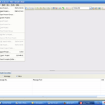
After we have got the FFT values we will make a sequence and will transfer them serially one by one. Most of the controllers support serial communication (RS232 protocol). We will make an array of FFT values of different brainwave types and will transmit this array serially.
So, in this way, we have successfully transformed the analog brainwave signal into the FFT values of different brainwave type and have imitated the TGAM1 chip and our sensor.
After building the bridge between theoretical and practical views, we can easily relate as to how and from where these values are coming. Though if we will try in real, there will be many more complications and points. Also, the result might be more complex with unexpected variations.
You may also like:


Filed Under: Brainwave, Tech Articles, Tutorials

Questions related to this article?
👉Ask and discuss on EDAboard.com and Electro-Tech-Online.com forums.
Tell Us What You Think!!
You must be logged in to post a comment.